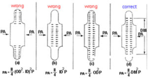
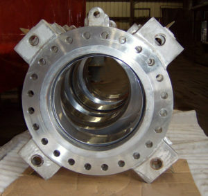
It is the force generated due to the pressure inside the expansion joint. Pressure thrust is calculated by multiplying the area of the mean bellows diameter by the pressure.
![]()
US Bellows is a Standards Subscriber | Exp: Dec 31, 2026 | See ejma.org to check verification process
Celebrating over 20 years of EJMA membership
Squirm pressure is the pressure at which in-plane instability occurs.
When engineers design fluid networks, a common question arises: Exactly what is a hydro test, and how do you determine the correct parameters?
A pipeline hydrotest ensures the structural integrity of the entire system before it enters active service. During this procedure, the piping is filled with liquid to apply hydrostatic water pressure against the internal walls of the entire system.
Industry standards require that the hydrostatic test pressure be calculated as a specific multiplier of the maximum design pressure, corrected for the temperature to ensure its operational integrity. The specific multiplier and correction factor will vary based on the piping design code.
Establishing the correct hydro test pressure validates the safety of welded joints and mechanical connections. This careful evaluation also applies to the pressure testing of valves to guarantee zero leakage under stress.
When determining the pressure for hydrostatic testing of your expansion joints, the most important aspect is the applicable design codes. Normally, the ASME SEC VIII Div.1 general hydro-test pressure will be 1.3 x design pressure, but if you are testing for ASME B31.1, B31.3,B31.4, it will be 1.5 x design pressure.
That being said, there are many other considerations that will determine the test pressure, such as:
Be sure to discuss with our engineers so that we can correctly test your bellows and expansion joints.
| Pressure thrust load is calculated by finding the area of the mean diameter of the bellows and multiplying it by the design pressure. |
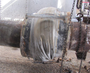
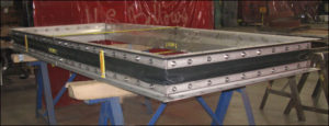
Rubber bellows can crack if they are over-pressurized or placed in a harsh environment.
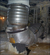
Failures can occur for many reasons, but experience has shown that certain causes of failure fall into fairly distinct categories.
Shipping and handling damage. Examples: Denting or gouging of bellows from being struck by hard objects (tools, chain falls, forklifts, adjacent structures, etc.); improper stacking for shipping or storage; insufficient protection from weather or other adverse environmental conditions.
Improper installation and insufficient protection.
During and after installation.
Examples: Joints with internal liners installed in the reverse direction with respect to flow; installing an expansion joint in a location other than as prescribed by the installation drawings; premature removal of shipping devices; springing of bellows to make up for piping misalignment; insufficient protection from mechanical damage due to work in the surrounding area; insufficient protection of bellows during nearby welding operations and failure to remove shipping devices before placing system in operation.
Improper anchoring, guiding and supporting of the system.
Anchor failure in service.
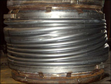
Bellows corrosion, both internal and external.
System over-pressure (in-service or hydrotest). Bellows vibration (mechanical or flow-induced resulting in high cycle fatigue).
Excessive bellows deflection (axial, lateral, angular deflections greater than design values).
Torsion.
Bellows erosion.
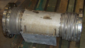
The failure mode of bellows could be any of a variety of things including erosion, corrosion, cyclic fatigue or thermal creep at elevated temperatures.
Regarding the operating temperature, we design metal pipe expansion joints up to 2000° F with refractory and 1000° F to 1500° F without refractory.
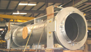
Toroidals can be used but not often. Most exchanges use normal thin-wall expansion joints or thick-wall expansion joints fabricated from flanged and flued heads.
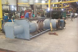
The weight of the units is self-supporting but the additional weight of the piping, elbows etc. in the field will not be supported by the expansion joint.
Yes, this is one of the expansion joint functions
Read MoreNo, it is the total of the spring rates of all three bellows.
Read More
The number of expansion joints used in a pipe depends on the length of the pipe, the pressure, the temperature, and the size. Upon knowing these design conditions, we can inform you of the number of expansion joints the pipeline requires.
Read MoreAn expansion joint is used to absorb dimensional changes, such as those caused by thermal expansion or contraction of a pipeline, duct, or vessel.
The expansion joint used for fuel oil and fuel gas applications depends on the movement and design conditions of the particular application within the plant.
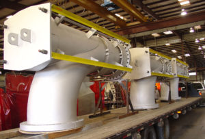
The spring rate is equal to the spring rate of both flow bellows plus the spring rate of the balancing bellows.
Expansion joints are needed to absorb thermal movement when piping flexibility will not solve the problem.
Expansion joints are required anywhere throughout the plant where thermal expansion must be absorbed. One example where expansion joints may be used in a power plant would be on piping running to power turbines or condensers.
It is recommended that all expansion joints include liners in order to protect the bellows from the internal flow environment.