|
The pressure thrust produced by low pressures can be tremendous in large diameter systems, just as it can be at normal pressure ratings in small pipes. To avoid expensive anchors, to keep long pipe runs in tension, to prevent buckling, or reduce reaction forces on equipment, the pressure in the pipe can be used to generate balancing forces within the pipe expansion joint. These combinations of bellows and thrust restraining structural components can accept almost any combination of movements, as shown in the following examples. |
||
 |
 |
 |
|
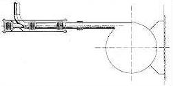
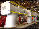
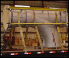
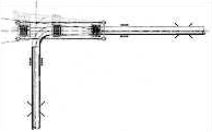
36″ Pressure Balanced Elbow Pipe Expansion Joints
|
||
|
|
||
|
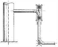
The pressure balanced elbow is ideal for absorbing the thermal expansion of equipment, such as turbines, pumps and compressors, which rely upon low reaction forces on their inlet and exhaust flanges. In this example, only an intermediate anchor is provided at the elbow, to isolate the equipment from any forces produced in the remaining piping. The pressure thrust force produces tension on the equipment flange, but the only forces produced by the deflection, are the spring resistance of the bellows within the pipe expansion joint. The spring rate of these units is the sum of the spring rates of the bellows on each side of the elbow, and care must be taken to provide a unit which produces spring forces low enough to satisfy the equipment maximums as stated by the equipment manufacturer. Bellows may also be cold sprung to reduce these forces even lower. |
||
|
|
||
|
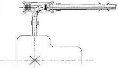
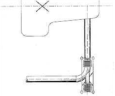
In this example, which may be typical for a turbine exhaust application, the force on the machine’s flange is the spring reaction of the bellows in lateral deflection, as described in Example 12. Again, the flange is also subjected to an axial force equal to the pressure thrust, as if it were capped, but the turbine’s mounts are not. The pipe guide between the expansion joint and the equipment flange absorbs the forces produced by the thermal expansion of the pipe, along its axis. When the pipe expansion joint must be located adjacent to the equipment flange, the elbow of the expansion joint can be used as an intermediate anchor point as shown below. |
||
 |
||
| Now, all radial growth of the machine is absorbed by the pipe expansion joint as axial deflection. Axial machine growth creates lateral deflection. | ||
 |
||
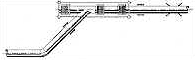
| The vertical growth of a tank or vessel is handled easily as shown. The advantage of pressure balancing is that the vessel is not subjected to an unbalanced side load from the pressure thrust at the nozzle. Radial growth of the vessel is accepted by the pipe expansion joint as lateral deflection. With an intermediate anchor at the pipe elbow near the ground to isolate downstream pipe movement from the vessel, a guide is added near the pipe expansion joint to eliminate or limit pipe bending. | ||
 |
||
|
In the previous examples, a single bellows was shown as the primary, or working bellows. When lateral movements are large, or lateral spring forces must be minimized, the primary bellows is a universal type as shown above. |
||
|
|
||
|
Most often the elbows in pressure balanced pipe expansion joints are 90 degrees. They can be provided with any degree angle elbow and they will function the same way as is shown with the 45 degree pressure balanced elbow above. |
||
![]()
US Bellows is a Standards Subscriber | Exp: Dec 31, 2026 | See ejma.org to check verification process
Celebrating over 20 years of EJMA membership