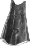
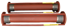
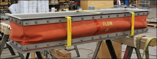
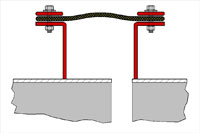
Fabric pipe expansion joints are often used in ducts which carry hot gases at low pressures. The major design parameters are the temperatures and flow rates of the gases and the amount and abrasiveness of solids suspended in the gases. Layers of different fabrics insulation can be combined to accommodate the temperatures and pressure in the system. The fabric belt may need to be replaced periodically.
Q: What makes a fabric expansion joint suitable for extreme heat applications?
A: When designing high-temperature expansion joints, engineers incorporate specialized layers of thermal insulation and a durable fabric expansion joint cloth to protect the outer gas-tight sealing layer. Depending on the thermal resistance and characteristics of each layer of insulating fabric, will determine the thickness of the insulation. Engineers must also consider the steel material of the frame to make sure it is suitable for the high temperatures.
Q: Can a single fabric expansion joint absorb multiple types of movement at the same time?
A: Yes. Unlike rigid metallic alternatives, the highly flexible nature of fabric expansion joint material allows a single assembly to absorb large amounts of axial, lateral, angular and even torsional movement simultaneously.
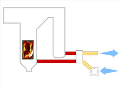
Fabric expansion joints perform a function of compensating for duct misalignment and duct thermal growth typically in power plants and other ducting systems. Fabric expansion joints are found wherever there is a need to convey hot media in low pressure applications such as “in flowing air” and “out flowing gas” in large combustion processes.
Fabric expansion joints can absorb larger movements than metal expansion joints and do so without spring loads. This is critical to limiting thermally induced stresses in ducting, ducting supports, and related equipment.
How Does a Fabric Expansion Joint Work?
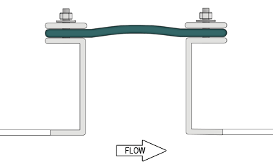
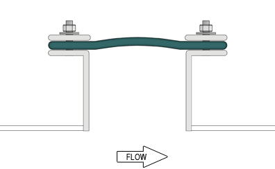
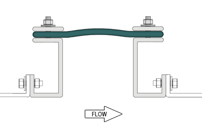
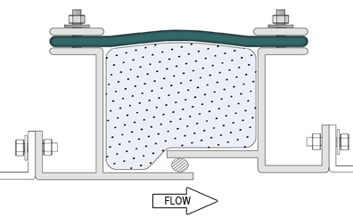
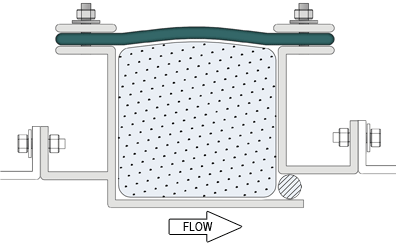
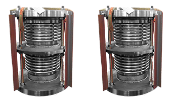
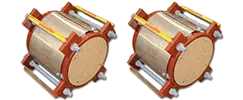
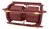
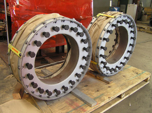
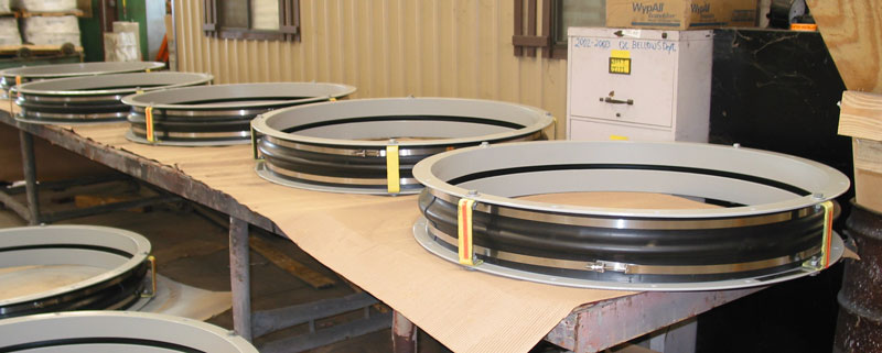
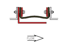
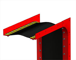
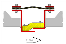
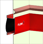
A fabric expansion joint is inserted into a gap in the duct work where movement will occur. A fabric expansion joint has two main components — the fabric gas seal and the metal frames. The fabric gas seal is a closed loop, like a belt, with its two edges clamped all around to the metal frames that are in turn connected to the end of ducting. As the ducting moves, the fabric belt deforms. The fabric material must do this without tearing or leaking while sometimes being exposed to high temperatures and/or corrosive media.
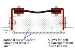
In some instances, additional components such as insulation pillows, accumulation barriers or flow liners are utilized to help protect the fabric material. The following section describes the basics of fabric expansion joint components and how they are designed.
Design Integration for Fabric Expansion Joints
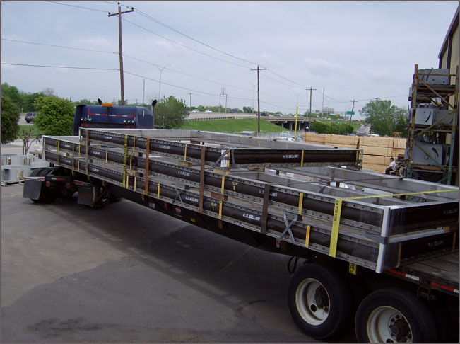
In addition to fabric expansion joints, U.S. Bellows is a major designer and fabricator of ducting. Design Integration is the design, manufacture and shipping of expansion joints integrated into the ducting as a complete unit directly from U.S. Bellows. This enables U.S. Bellows to offer optimum system design and the lowest installed cost.
Design Integration Advantages:
Elimination of flanged connection gasketing and potential leaks.
Elimination of the risk of installing sensitive assemblies at the job site.
Significant costs savings of both manufacturing and installation labor.
Delivery of the largest “shippable” duct and piping sections to the job site to eliminate as many filed connections as possible, further reducing installation labor.
Minimize the number of flanged expansion joint connections.
Allows integration of ducting to serve as expansion joint flow liner.
Allows expansion joint frames to take the place of duct stiffeners.
Elimination of labor to install flanged expansion joint assemblies at the job site.
U.S Bellows has considerable experience in design and fabrication of integrated ducting with metal and fabric expansion joints. U.S. Bellows is also very knowledgeable with transportation capabilities for wide and heavy loads and can make firm commitments “up-front” for the largest shippable size and heaviest weight.
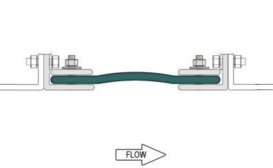
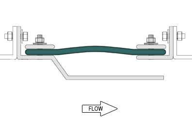
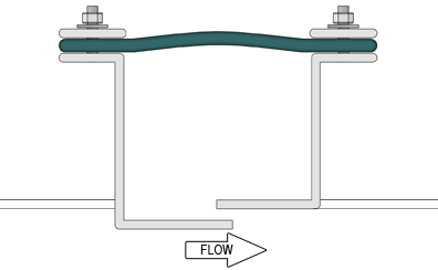
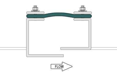
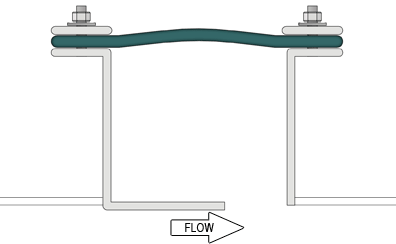
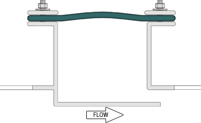
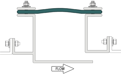
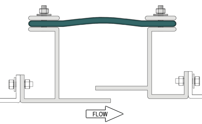
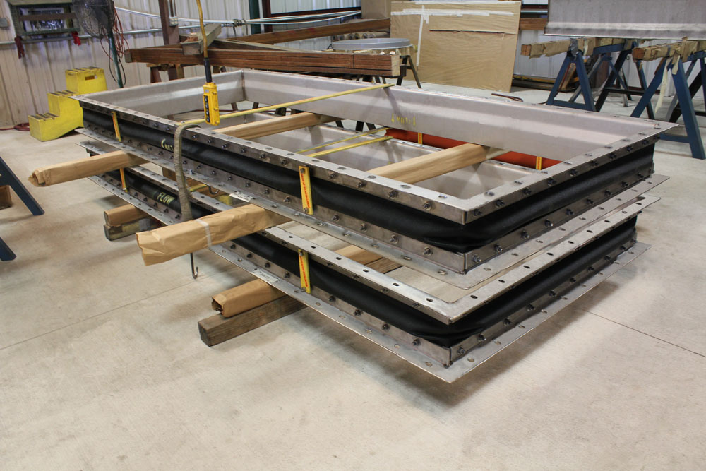
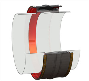
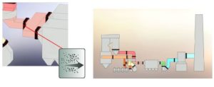
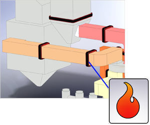
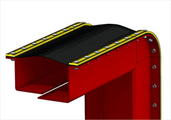
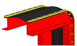
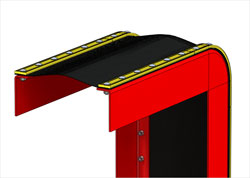
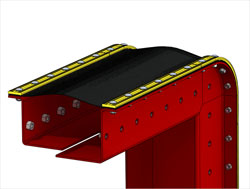
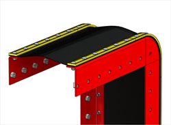
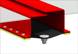
The drawing below shows a cross section of an expansion joint designed to allow the ducting to serve as a flow liner. The joint frame takes the place of a stiffener flange. The complete duct/expansion joint ships as one factory assembled component.
FABRIC EXPANSION JOINTS AND FACTORS INFLUENCING THEIR DESIGN
Fabric expansion joints perform a function of compensating for duct misalignment and duct thermal growth typical in power plants and other ducting systems. Proper design of these joints starts with asking the right questions about the application, providing the correct answers, and applying design rules to arrive at the appropriate solution.
The guiding principle for fabric joint design is to protect the fabric belt element so that it can absorb movement while retaining the media. The longevity of the belt life can be diminished by many factors. These factors include excessive temperature, harsh corrosives, exposure to abrasive particulate, excessive movements, fly ash weight against the belt, and high internal pressures. All of these problems can be solved if they are anticipated. The quality of the expansion joint design is only as good as the information provided up front. A realistic and accurate analysis of the system is step one. Assuming that is taken care of, these guidelines are a brief introduction to factors that influences the success of the expansion joint.
TEMPERATURE
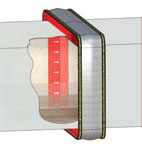
Fabric gas seal membranes have specific temperature capabilities. When necessary, the addition of insulating materials between the temperature source and the belt will extend the service life. The magnitude of the temperature will determine the thickness of the integral belt insulation and if a separate high density insulation pillow is required.
The belt attachment flanges should be outboard of the cavity and have sufficient standoff from the duct. Care should be taken to avoid external insulation or lagging outside of the belt which prevents proper heat dissipation.
CHEMICAL ATTACK
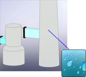
Applications that do not have high temperatures sometimes have a different problem. Relatively low temperatures in flue gas ducting can lead to corrosive condensation. In these situations, a chemical barrier is required to protect the load bearing fiberglass carcass of the belt. External insulation over the joint in these locations can reduce condensation and heat loss.
MOVEMENTS
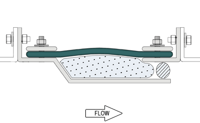
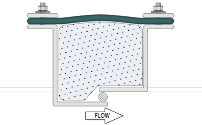
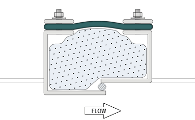
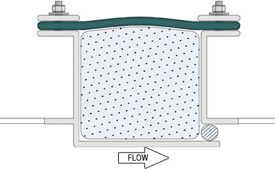
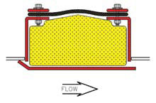
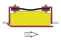
Generally, movements occur along the axis of the duct (usually compression but occasionally extension) or at right angles (lateral). The key to being able to handle these movements is having the proper width of belt installed in a sufficient span. For compression, a ratio of installed belt span to movement roughly at 4:1 is suggested. The lateral capability is influenced by the amount of belt slack available. Concurrent axial compression will provide the slack thus allowing more lateral. In certain situations, there is lateral offset in the cold installed condition. This may require “pre-compression” of the joint which is in essence just providing extra belt width.
ABRASION
In flue gas ducting with particulate, a liner should be used to protect the belt from direct exposure. If the pressure is negative, the belt stand-off from the gas stream should be increased to keep the belt from being pulled into the gas stream or against the liner. Belt clamping bar edges next to the fabric should be radiused. The belt attachment flange should also be smooth and free of rough surfaces.
PRESSURE FLUCTUATIONS
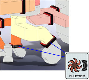
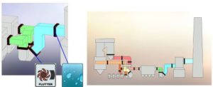
Fabric expansion joints exposed to sudden pressure fluctuations, such as near ID fans and dampers, may result in the belt “fluttering”. The fabric will fatigue over time resulting in tears. Using stiffer fabric material, installing a liner and increasing the standoff are steps to take to avoid flutter.
SUMMATION
Each location throughout a ducting system can have different conditions that affect the design of expansion joints. As a result, there isn’t one design that can fit all applications. The goal of the expansion joint supplier is to work with engineers and end users to provide the optimum economical solutions.
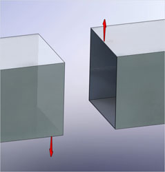
Directional Movement for Fabric Expansion Joints
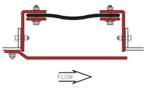
Axial Compression
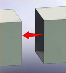
The reduction in the breach opening along the axis of the duct. This is usually a result of thermal expansion of the ducting.
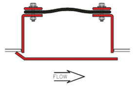
Axial Extension
The increase in the breach opening along the axis of the duct. In certain configurations, the duct thermal expansion may result in extension at the expansion joint location.
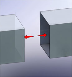
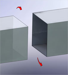
Lateral Movement
The relative movement of the upstream and downstream faces in the direction perpendicular to the axis of the duct.
Torsional Rotation
The twisting of one side of the duct about the longitudinal axis.
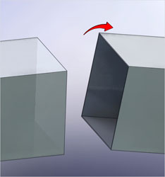
Angular Rotation
The twisting of one side of the duct about an axis perpendicular to the longitudinal axis.
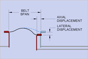
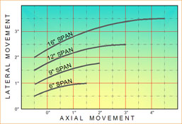
Fabric Expansion Joint Movement Chart
The chart shown above depicts the relationship of belt span, maximum compression and concurrent lateral movements. The maximum compression is a percentage of the available belt span (shown as the right end of the plot line). The wider the span, the more capacity for compression. The lateral capacity is a function of the belt slack created with concurrent compression.
As the compression increases, more belt material is available to safely allow movement without over-stressing the fabric material. In situations with large lateral movement and little compression, the joint can be installed pre-compressed to have more lateral capacity.
When in doubt, allow experienced U.S. Bellows engineers to help select the correct span for each particular application.
Similar Applications:
Fossil Fired Power Plant, Gas Recirculation System, Pulp and Paper Plant, Recovery Boiler to Precipitator, Refinery Turbo-Expander to CO Boiler and CO Boiler to Precipitator, Cement Plant, Clinker Cooler to Heat Exchanger
Typical Conditions:
650°F to 850°F operating temperature, -10″ to -25″ WG pressure, fuel gas media with heavy particulate. Boiler growth contributes to large axial or lateral expansion joint movements depending on joint orientation.
Sample Data Sheet:
High Temperature Dirty Flue Gas Expansion Joint Applications
Recommended Expansion Joint Designs
Common Design Features:
Fabric Belt: Un-insulated fabric material (FLEXXCEL HD7)
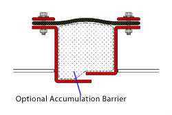
Accumulation Barrier: Fills joint cavity to reduce particulate buildup
Liner: Flow liner retains barrier and protects the belt from abrasion
Style 200W
Design Performance: *****
Manufacturing Cost: $$$
Installation Cost: $$
Unique Features: Integral telescoping liners to retain accumulation barrier and protect belt from abrasion.
Design Performance: **
Manufacturing Cost: $$$$
Installation Cost: $$$$
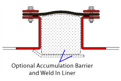
Unique Features: Field weld liner, Ease of pre-compression for installing in breech opening, Requires belt attachment nuts to be tack welded, Leakage around belt attachment fasteners possible.
Style 700WDesign Performance: ***
Manufacturing Cost: $$$
Installation Cost: $$$
Unique Design Features: Belt installed and replaced from inside the duct, Field weld liner, Ease of pre-compression for installing in breech opening, Requires belt attachment nuts to be tack welded, Leakage around belt attachment fasteners possible.
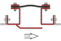
Turbulent Flue Gas and Wet Gas Expansion Joint Applications
Similar Applications
Pulp and Paper Plant, Primary Air to Recovery Boiler
Typical Conditions
Ambient temperature, 40″ to 50″ WG pressure, Clean air Movement mainly limited to vibrations
Sample Data Sheet for Listed Applications
Data Sheet for Turbulent Air Expansion Joint Applications
Recommended Expansion Joint Designs
Common Design Features:
Fabric Belt: At fan locations, a flutter resistant fabric belt material should be used. (FLEXXCEL FF1)
Standoff: Bolt-in design for attachment to equipment or duct flanges.
External duct insulation: Flow liner to reduce turbulence/flutter of fabric belt material. Style 200B
Design Performance: *****
Manufacturing Cost: $$$$
Installation cost: $$$$
Unique design features: Integral telescoping liners. Does not require tack welding nuts.
Style 100B
Design Performance: ****
Manufacturing Cost: $$$
Installation cost: $$$$$
Unique design features: Field weld liner. Does not require tack welding nuts.
Style 300B
Design Performance: ****
Manufacturing Cost: $$$$
Installation cost: $$$
Unique design features: Integral liner. Ease of pre-compression for installing in breech opening.
Style 400B
Design Performance: ***
Manufacturing Cost: $$$
Installation cost: $$$
Unique design features: Integral liner. Ease of pre-compression for installing in breech opening. Requires belt attachment nuts to be tack welded.
Style 500B
Design Performance: ***
Manufacturing Cost: $$$
Installation cost: $$$
Unique design features: Bolt-on liner. Flanges on fabric belt attach directly to duct flange or equipment.
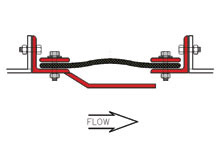
Turbulent Flue Gas and Wet Gas Expansion Joint Applications[/caption] Similar Applications
Fossil Fired Power Plant, Air Heater to Coal Pulverizers, Cement, Clinker Cooler to Heat Exchanger
Typical Conditions
600°F to 750° operating temperature, 5″ to 80″ WG pressure, Clean air media, Boiler growth contributes to large axial or lateral expansion joint movements depending on the orientation of the joints.
Sample Data Sheet for Listed Applications
Data Sheet for High Temperature Clean Air Applications
Recommended Expansion Joint Designs
Common Design Features:
Fabric Belt: High temperature fabric belt. (FLEXXCEL HT1, HT3, or HT5 depending on maximum temperature.)
Standoff: 6″ minimum standoff and outboard belt attachment flanges to dissipate heat.
External duct insulation: contoured around expansion joint to allow heat dissipation. (See page xx for details.)
Style 200W
Style 200W
Design Performance: *****
Manufacturing Cost: $$$
Installation cost: $$
Unique design features: Field weld frame to duct. Integral telescoping liners to increase fabric material life.
Style 100W
Design Performance: ****
Manufacturing Cost: $$
Installation cost: $$$
Unique design features: Field weld frame to duct. Field weld liner to increase fabric material life.
Style 300W
Design Performance: ****
Manufacturing Cost: $$$$
Installation cost: $$$
Unique design features: Field weld frame to duct. Integral liner to increase fabric material life. Designed for large breech openings
Style 200B
Design Performance: *****
Manufacturing Cost: $$$$
Installation cost: $$$$
Unique design features: Integral telescoping liners to increase fabric material life. Bolt in design for attachment to equipment or duct flanges. Does require tacking welding nuts. Critical information required to insure proper fit-up.
Style 100B
Design Performance: ****
Manufacturing Cost: $$$
Installation cost: $$$$$
Unique design features: Field weld liner to increase fabric material life. Bolt in design for attachment to equipment or duct flanges. Does require tack welding nuts. Critical information required to insure proper fit-up.
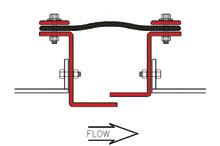
Dirty Flue Gas Expansion Joint
Similar Applications
Cement Plant, Preheat Tower, Refinery, CO Boiler to Precipitator
Typical Conditions
250° F to 500° operating temperature, -35″ to -50″ WG pressure, Flue gas with possibly fly ash carryover through air heater, Moderate thermal movements in ducting.
Sample Data Sheet for Listed Applications
Data Sheet for Dirty Flue Gas Expansion Joint Applications
Recommended Expansion Joint Designs
Common Design Features:
Fabric Belt: Un-insulated fabric material. (FLEXXCEL HD7)
Accumulation barrier: Fills expansion joint cavity to minimize the accumulation of particulate.
Liner: Flow liner to retain the accumulation barrier and protect the belt from abrasion.
Style 200W
Style 200W
Design Performance: *****
Manufacturing Cost: $$$
Installation cost: $$
Unique design features: Integral telescoping liners to retain the accumulation barrier and protect the belt from abrasion.
Style 600W
Design Performance: **
Manufacturing Cost: $$$$
Installation cost: $$$$
Unique design features: Field weld liner. Ease of pre-compression for installing in breech opening. Requires belt attachment nuts to be tack welded. Leakage around belt attachment fasteners possible.
Style 700W
Design Performance: ***
Manufacturing Cost: $$$
Installation cost: $$$
Unique design features: Belt installed and replaced from inside the duct. Field weld liner. Ease of pre-compression for installing in breech opening. Requires belt attachment nuts to be tack welded. Leakage around belt attachment fasteners possible.
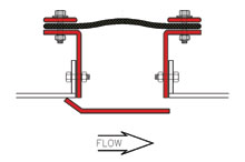
Turbulent Flue Gas/Wet Gas Expansion Joint
Similar Applications
Fossil Fired Power Plant, Re-heater to chimney, Pulp and Paper Plant Induced Draft Fan to Chimney, Refinery, Steam Generator to Stack
Typical Conditions
250° F to 500° F operating temperature, -35″ to +50″ WG pressure, Minimal particulate downstream of precipitator. Potential for wet conditions.
Sample Data Sheet for Listed Applications
Turbulent Flue Gas, Wet Gas Expansion Joint Applications Data Sheet
Recommended Expansion Joint Designs
Common Design Features:
Fabric Belt: At fan locations, the belt material should have a high resistance to flutter. (FLEXXCEL FF1)
Frame Attachment: Bolt-in design for attachment to equipment or duct flanges. (If equipment or duct flanges are not present, weld in designs are recommended.)
Liner: Flow liner to reduce turbulence/flutter of fabric belt material. Style 200B
Design Performance: *****
Manufacturing Cost: $$$$
Installation cost: $$$$
Unique design features: Integral telescoping liners. Does require tack welding nuts.
Style 300B
Design Performance: ****
Manufacturing Cost: $$$$$
Installation cost: $$$$
Unique design features: Integral liner. Ease of pre-compression for installing in breech opening. Does not require tack welding nuts.
Style 400B
Design Performance: **
Manufacturing Cost: $$$$
Installation cost: $$$$
Unique design features: Integral liner. Ease of pre-compression for installing in breech opening. Requires belt attachment nuts to be tack welded. Not recommended in negative pressure applications before ID fan.
Style 500B
Design Performance: **
Manufacturing Cost: $$$
Installation cost: $$$
Unique design features: Bolt-on liner. Flanges on fabric belt attach directly to duct flange or equipment. Not recommended in negative pressure applications before ID fan.
Similar Applications
Fossil Fired Power Plant, Scrubber Bypass to Stack and Scrubber to Re-heater Pulp and Paper Plant, Scrubber Inlet and Scrubber to Re-heater
Typical Conditions
120° F to 350° F operating temperature, +5″ to +15″ WG pressure, Minimal particulate. Highly corrosive wet gas, Minimal movements.
Sample Data Sheet for Listed Applications
Low Temperature Wet Flue Gas Expansion Joint Applications Data Sheet
Recommended Expansion Joint Designs
Common Design Features:
Fabric Belt: Fabric material should have the maximum chemical barrier due to corrosive conditions. (FLEXXCEL HC40) Style 100W
Design Performance: *****
Manufacturing Cost: $$
Installation cost: $$$
Unique design features: Welds to duct.
Style 300W
Design Performance: ****
Manufacturing Cost: $$$$
Installation cost: $$$
Unique design features: Ease of pre-compression for installing breech opening. Does not require tack welding nuts.
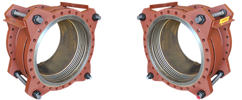
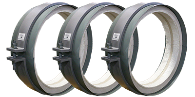
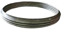
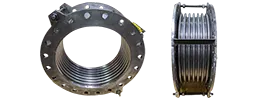
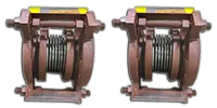
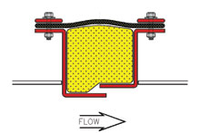
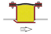
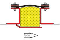
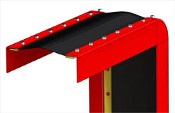
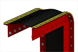
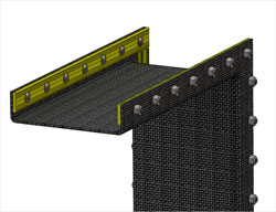
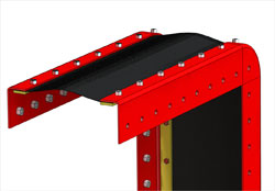
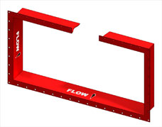
Fabric expansion joints consist of two major components– the fabric belt material and the metal frame. The frame can connect to the ducting by welding or bolting.
Each U.S. Bellows frame style has features designed to minimize the detrimental effects of temperature, movements, pressure, media, and turbulence. The U.S. Bellows team is experienced in evaluating application conditions and implementing designs that lead to long term expansion joint service.
Design alterations can include the following:
Adequate stand off height
Adequate face to face dimension
Inclusion of liner
Frame material
Belt material
Inclusion of accumulation barrier
Inclusion of insulation pillow
Proper bolt hole spacing
And more
Although U.S. Bellows can provide weld-in and bolt-in frame styles, wherever possible, it is strongly recommended that the expansion joint be welded in place.
Weld in Designs
Weld in Design frame styles allow the expansion joint to weld directly to the duct or duct flanges. These frames styles are basic designs that can be augmented with optional components.
Benefits of weld in designs include:
Weld in designs are less expensive to manufacture.
Accurate field bolt hole dimensional data can be difficult to obtain and verify.
Welded connections can accommodate “real world” field conditions and inaccuracies that occur during installation.
Bolt In Designs
Bolt In Design frame styles allow the expansion joint to bolt directly to duct flanges or equipment flanges supplied by others. These frame styles are basic designs that can be enhanced with the optional components.
Frame Design Components
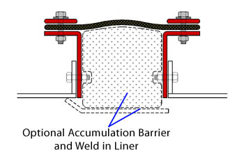
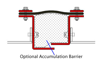
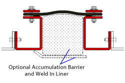
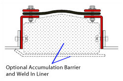
Accumulation Barrier For Applications with Particulate
Insulation Pillow for High Temperature Applications
Bolt-On Liner for Style 500
Bolt-On Liner for Style 700
Weld on Liner for Styles 100, 600
Drain
Particulate Deflector
Weld In Designs
Design Feature Legend:
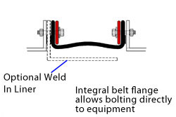
Outboard belt attachment flanges keep fabric metal cool at the attachment area.
Provides standoff of fabric belt from media.
Flat belt design for maximum belt life, ease of replacement, and composite construction options.
Inboard flanges should not be used in applications where the temperature exceeds the fabric material rating.
Integral telescoping liners offer the best protection from abrasion .
Superior design for pinning insulation pillows to liners.
Requires tack welding nuts to frame.
Style
Design Features
Typical Cross Sections
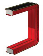
Rectangular Expansion Joint with Typical Corner Details
100-W
1, 2, 3
200-W
1, 2, 3, 5, 6
300-W
1, 2, 3
600-W
2, 3, 4, 7
700-W
2, 3, 4, 7
The following frame styles allow the expansion joint to bolt directly to duct flanges or equipment flanges supplied by others. These frame styles are basic designs that can be enhanced with the optional components.
Design Feature Legend:
Outboard belt attachment flanges keep fabric metal cool at the attachment area.
Provides standoff of fabric belt from media.
Flat belt design for maximum belt life, ease of replacement, and composite construction options.
Inboard flanges should not be used in applications where the temperature exceeds the fabric material rating.
Integral telescoping liners offer the best protection from abrasion .
Superior design for pinning insulation pillows to liners.
Requires tack welding nuts to frame.
Style
Design Features
Typical Cross Sections
Rectangular Expansion Joint with Typical Corner Details
100-B
1, 2, 3, 7
200-B
1, 2, 3, 5, 6, 7
300-B
1, 2, 3
400-B
3, 4, 7
500-B
4
600-B
2, 3, 4, 7
700-B
2, 3, 4, 7
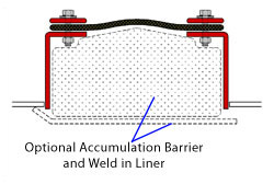
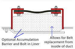
Accumulation Barrier For Applications with Particulate
The accumulation barrier option provides a flexible, low density barrier for fly ash or dust accumulation in the expansion joint cavity. It can be provided for any design that includes a flow liner. The barrier typically is constructed with low density fiberglass material wrapped in aluminized fiberglass cloth and wire mesh. In applications with large movements, the barrier can be constructed with “ears” that are clamped under the backing bars.
Insulation Pillow for High Temperature Applications
The insulation pillow option ensures that the temperature at the gas seal membrane does not exceed it’s capability. The insulation pillow is constructed with high density needle felted ceramic insulation wrapped with high temperature cloth and wire mesh. The insulation pillow is pinned snuggly to the liners or frames.
Bolt-On Liner for Style 500
The liner is attached with the fasteners of the upstream clamping bar.
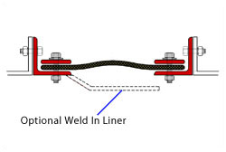
Bolt-On Liner for Style 700
The liner is designed to be removed from inside the ducting to allow access to the fabric belt. The liner is attached with studs field welded inside the duct.
Weld on Liner for Styles 100, 600
The liner is field welded to the upstream inside edge of the duct. (3D view similar to Style 700 except without studs.
Drain
A drain fitting machined out of PTFE material can be installed in the belt at the bottom of the expansion joint. If conditions are wet enough to cause pooling, specify a drain.
Particulate Deflector
In certain conditions, a particulate deflector can be specified to reduce air born particulate from falling down into the expansion joint cavity. This is most common on vertical ducting with the flow direction up and an upstream liner overlapping the downstream duct. The deflector presents an angled surface to the flow and eliminates a ledge for build-up.
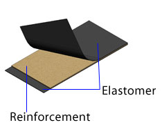
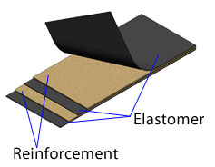
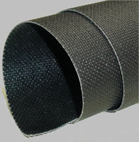
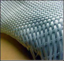
Fabric belt material selection is a critical factor in the successful design of each fabric expansion joint. A number of materials are widely accepted for use in fabric expansion joint applications. These materials fall into two general families—Fluoroplastics and Elastomers.
Chemical resistance, temperature limitations, abrasion resistance, tensile strength and susceptibility to flutter/vibration are major considerations when selecting a fabric material. Please review the following section for details regarding FLEXXCEL Fluoroplastic products.
Fluoroplastics (PTFE)
Fluoroplastics (PTFE) – The chemical resistance of this material is unequaled by other materials.
Find more information on Fluoroplastic (PTFE) Materials:
Elastomers – A general name for the group of synthetic “rubber” materials that are characterized by their elastic property. These materials are also known by their commercial names as Viton®, Hypalon®, EPDM, and Chlorobutyl.
Fluoroplastics (PTFE) — The chemical resistance of this material is unequaled by other materials.
Chemical resistance, temperature limitations, abrasion resistance, tensile strength and susceptibility to flutter/vibration are major considerations when selecting a fabric material. Please review the following section for details regarding FLEXXCEL Fluoroplastic products.
Fiberglass substrate is thoroughly coated on both sides with a minimum of 35% to 40% by weight of PTFE resin for mechanical strength.
Fluoroplastic coating is 100% pure PTFE material.
Fiberglass reinforcement filaments are E grade or better, providing excellent tensile strength.
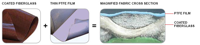
FLEXXCEL MD4 and HD4 = FOR DRY SERVICE
Extruded, thin single ply film laminated to coated fiberglass.
All FLEXXCEL materials have a chemical barrier film to protect the fiberglass substrate and minimize porosity. The chemical barrier component of these materials is in the form of a film that is laminated to the fiberglass cloth.
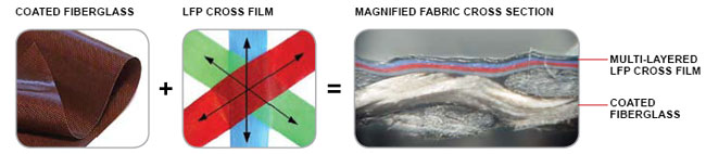
FLEXXCEL MD7, HD7, HD12, and HD20 = FOR WET SERVICE
LFP CrossFilm based chemical barriers are laminated to the coated fiberglass. The use of LFP CrossFilm Chemical Barriers provides superior protection in corrosive environments.
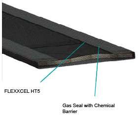
A zero porosity chemical barrier is the most critical component for preventing chemical attack.
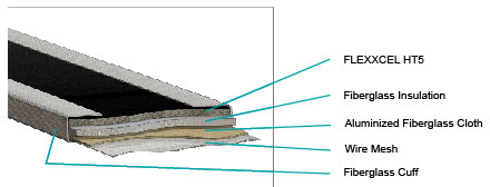
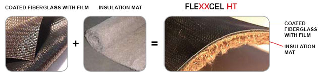
FLEXXCEL HT1, HT3, and HT5 = FOR HOT-DRY SERVICE
FLEXXCEL HT series fabric belts rated for temperatures up to 1000°F. Insulation is bonded to FLEXXCEL HD4 material to prevent hot gas from residing between the two components.
Extends like of insulation component.
Prevents insulation from falling into duct.
Makes installation of high temperature composite belts easier.
A zero porosity chemical barrier is the most critical component for preventing chemical attack.
Flexxcel Fluoroplastic Belt Materials
Fluoroplastic materials have been successfully used in challenging expansion joint applications since the early 1980’s. The expansion joint fabric is composed of two components— PTFE resins and fiberglass cloth. The fiberglass is used to give the fabric strength. The fiberglass can be of varying weights to give the fabric material the necessary tensile strength. The fiberglass alone is susceptible to degradation from chemicals and liquids. By thoroughly coating all surfaces of the fiberglass filaments, a strong and flexible base material is created. This base material can then be laminated to a PTFE film (Chemical Barrier) of varying thickness to provide a non-porous and chemically inert gas seal. Its virtual inertness to most chemicals make it an excellent choice for applications in wet corrosive environments.
Fluoroplastics also retain their structural integrity at extremely high or low temperatures, i.e., 600 degrees F to -110 degrees F (uninsulated). Fluoroplastics are capable of withstanding temperatures in excess of 1500 degrees F when properly insulated (composite belt).
Features of Fluoroplastics
High strength to weight ratio. Easier to handle and install compared to Elastomers.
Simple splice and repair by means of heat seal iron. Material does not age like Elastomers and therefore can be repaired for the life of the material.
Temperature capability up to 600 degrees F without additional insulation.
Materials are easy to drill and punch.
Guide to Selecting a Fluoroplastic Belt Material
Compare the maximum continuous operating temperature of the application against the fabric temperature rating.
If the application has high fly ash or dust loading, select a material with high tensile strength. (Fluoroplastic materials are susceptible to failure from abrasion. In applications where the media includes particulate, a liner must be present.)
If the application is near a fan or anywhere flow turbulence is expected, select a material with high flutter resistance.
In areas of scrubbers or applications that experience condensation of low temperature gases, select a material for wet service.
For areas where corrosion is most severe, we recommend FLEXXCEL HC40.
Material Name
Temp. (F)
Service
Tensile Strength
Chemical Barrier Thickness
Flutter Resistance
Relative Cost
FLEXXCEL MD4
600
Dry
Medium
4 mil
Low
$
FLEXXCEL HD4
600
Dry
High
4mil
Low
$
FLEXXCEL MD7
600
Wet
Medium
9 mil
Low
$$
FLEXXCEL HD7
600
Wet
High
9 mil
Low
$$
FLEXXCEL HD12
600
Wet
High
12 mil
Low
$$$
FLEXXCEL HD20
600
Wet
High
20 mil
Medium
$$$$
FLEXXCEL HC40
500
Wet
Medium
40 mil
Medium
$$$$$
FLEXXCEL FF1
600
Wet
Very High
9 mil
Very High
$$$$$
FLEXXCEL DP1
600
Wet
High
20 mil
High
$$$$
FLEXXCEL HT1
700
Dry
High
6 mil
High
$$$
FLEXXCEL HT3
850
Dry
High
6 mil
High
$$$
FLEXXCEL HT5
1000
Dry
High
6 mil
High
$$$
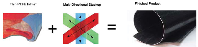
Flexxcel HC40 For Highly Corrosive Applications
*colors used to differentiate layers
LFP™ is an all PTFE material that is flexible, resists tearing and has superior flexing capabilities compared to other PTFE products.
Because this is an all-PTFE product with excellent mechanical capability, no compromising reinforcement that can be chemically attacked is needed.
Regardless of the chemical exposure, LFP™ eliminates concern for chemical attack. This has been proven in laboratory and industrial service where, in all cases and regardless of chemical environment, LFP™ has retained all of its physical properties.
Flexxcel FF1 For Flutter Applications
Engineered for turbulent flue gas conditions, FLEXXCEL FF1 is manufactured to a high weight without sacrificing the critical flexing properties require for a fabric expansion joint. Because of the high weight, it doesn’t move during operation except to flex due to thermal movements.
Constructed of 7 plies of Fluoroplastic and fiberglass insulation that are thermally welded together on regular intervals.
Flexxcel Fluoroplastic Applications Specific Materials
Engineered for applications above 1000°F, HT Composite Belt combines FLEXXCEL HT5 gas seal with an additional layer of fiberglass insulation and reinforced with a layer of cloth and wire mesh. The edges are held together with fiberglass cuffs that also serve as high temp gaskets.
Flexxcel DP1 Dew Point Belt
In flue gas ducts operating at or near dew point, a single ply fabric belt can present a cold surface for corrosive condensation to occur. In order to minimize heat loss at the belt and still allow access for inspection and replacement, a special belt construction—FLEXXCEL DP1 can be specified. The inner gas seal has a thick chemical barrier and the outer component has an integral layer of insulation. This belt construction reduces potential chemical attack to the ducting and expansion joint frame.
Elastomers – A general name for the group of synthetic “rubber” materials that are characterized by their elastic property. These materials are also known by their commercial names as Viton®, Hypalon®, EPDM, and Chlorobutyl.
Before the development of Fluoroplastics, a group of synthetic “rubber” materials were commonly used in flue duct expansion joint applications. These materials, known as Elastomers, include Viton™, EPDM, Chlorobutyl, Hypalon™ and others.
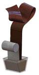
Because of their elastic properties, the various Elastomers are built up into a multi-layered sheet reinforced with fiberglass or Aramid fabric. The finished product, 1/8″ to 1/4″ thick, is then used as a flat belt or as an integrally flanged U-shaped cross section that bolts directly to duct or equipment flanges. The inherent characteristics of flexibility, abrasion resistance, and flutter resistance translates to long service life when applied properly.
Fluoroelastomer, also know as FKM or by it’s commercial name Viton®, is the most commonly used Elastomer in flue duct joints. It is a high performance material that resists acids and many other chemicals.
Please review the following section for details regarding FLEXXCEL Fluoroelastomer and Elastomer products.
Flexxcel Elastomeric Belt Materials
Though Elastomers have been used successfully in many applications since the 1960s, they have some limitations and drawbacks. The biggest limitation is the relatively low temperature capability (see Elastomeric Belt Material Guide). Compared to Fluoroplastics, they are heavy and as a result, can be more difficult to install. Splicing Fluoroelastomer material requires vulcanization—a curing process that involves high heat, pressure and the addition of sulfur as a curative. Splicing and repair is limited after the material ages. Fluoroelastomers are also less resistant to chemical attack than Fluoroplastics.
See our Elastomeric Belt Material Guide for the full line of Elastomeric materials that U.S. Bellows offers.
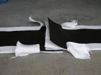
Typical 1/8″ thick Elastomeric fabric belt with single ply reinforcement
Typical 1/4″ thick Elastomeric fabric belt with two ply reinforcement
Guide to Selecting an Elastomeric Belt Material
Compare the maximum continuous operating temperature of the application against the fabric temperature rating.
If the application has high fly ash or dust loading, select a material with high tensile strength.
If the application is near a fan or where flow turbulence is expected, select a material with high flutter resistance.
Elastomers vary in their chemical resistance. The selected Elastomer should be checked to insure that it is compatible with the particular media it will encounter.
Material Name
Elastomer
Temp. (F)
Service
Tensile Strength
Flutter Resistance
Relative Cost
FLEXXCEL RH125
Hypalon
225
Dry
Medium
Medium
$
FLEXXCEL RE125
EPDM
300
Wet*
Medium
Medium
$$
FLEXXCEL RE25
EPDM
300
Wet*
High
High
$$$
FLEXXCEL RC125
Chlorobutyl
300
Dry
Medium
Medium
$$
FLEXXCEL RC25
Chlorobutyl
300
Dry
High
High
$$$
FLEXXCEL RVF25
Fluoroelastomer
400
Wet
Medium
Medium
$$$$$
FLEXXCEL RVF25
Fluoroelastomer
400
Wet
High
High
$$$$$$$$
FLEXXCEL RVF25M
Fluoroelastomer
400
Wet
High
High
$$$$$$$$$$
*Not suitable for sustained service where oils, hydrocarbons or concentrated minerals acids are present.
Temperature
Materials
Advantages
Pressure
Chemical Resistance
Applications
Low
Ambient - 250°F
Butyl Rubber
Neoprene
High tensile strength
Ozone and weathering resistance
Medium
High
Hot and Cold Water
Low Pressure Steam
Neutral Solutions
Medium
250 - 500°F
Fiberglass
Reinforced Silicone
Resistant to deterioration by weathering and engine oil remains
UV / ozone / fungus resistant
"Product on time (expedited), high quality, and documentation was well in order.”
US Bellows Metal Expansion Joints Operating Plant - May 2025
"Got my Bellows back quick.”
US Bellows Metal Expansion Joints Operating Plant - May 2025
"My impression of your technical and production engagement is very positive."
Expansion Joints Metal Bellows - January 2021
"I sincerely thank all of you for your efforts to date and encourage all of you to continue the excellent performance and commitment to the projects."
Single Expansion Joint - 2020
"Thank you very much for the excellent work you and your associates at PTP/USB provided on my order..."
High Temperature Insulated Supports - December 2021
"As a Mechanical Engineer, I like the products & complimentary webinars Piping Technology & Products offers."
Expansion Joints Metal Bellows - September 2022
"Work is always completed when they say that it will be completed."
Expansion Joints Metal Bellows - November 2022
"As always, I appreciate the prompt support provided by PT&P team and I know, I can count on it every time."
Expansion Joints Metal Bellows - November 2022
"US Bellows engineer has been really helpful in ensuring that we get this order expedited and that we make sure to iron out all the details to ensure we get the best product."
Expansion Joints Metal Bellows - March 2023
"Responsive team!"
Expansion Joints Metal Bellows - March 2023
"I cannot be happier to deal with the engineers at PTP. The quote process has been extremely easy...
Expansion Joints - April 2023
"The US Bellows team was very professional and help guide me through the process."


 Similar Applications
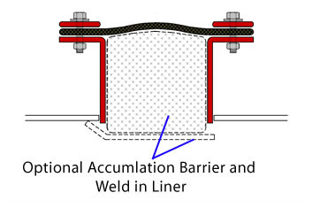


 *colors used to differentiate layers