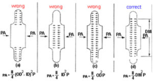
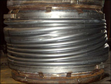
It is the force generated by the expansion joint due to the pressure inside. As shown in the picture, we have seen several incorrect ways to calculate the thrust force of an expansion joint. Per the EJMA Standards, as well as ASME Section VIII B&PV Codes, the Pressure thrust is calculated by multiplying the Bellows Effective Area, corresponding to the mean diameter of the convolutions of the Bellows by the Pressure of the line.
Bellows squirm because they have surpassed the critical design pressure limit. This can occur in small diameter bellows with a large number of convolutions.
Fabric Expansion Joints can withstand up to 3 PSIG (pounds per square inch gauge) or 100″ of water (H₂O) column (In pressure). If the pressure exceeds this amount, it is best to use a metallic expansion joint.
The pressure is equal on both sides for a pressure balanced expansion joint. If the pressure difference is minor, it would not be a problem, but if the pressure thrust is high, then an imbalance of forces would occur and could result in forces being transmitted to adjacent equipment.
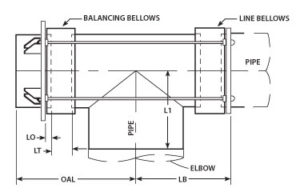
In an axial piping system, the expansion joint should be located as close as possible to a main anchor. The first pipe guide should be located at a distance of 4 pipe diameters away from the expansion joint. The second guide should be located a distance of 14 pipe diameters away from the first guide. During installation, the expansion joint should be either welded or flanged into the piping system.
Yes, if they are testing just the expansion joint or if they are testing when installed, they have to make sure that the pipe line is anchored or have limit rods added to the expansion joint to absorb the pressure thrust.
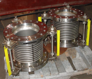
The pressure rating an expansion joint can take depends upon pipe size and temperature. Standard units from 3 inches to 24 inches are suitable for 300 PSIG. (pounds per square inch) Higher pressures can be accommodated on a case by case basis.
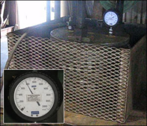
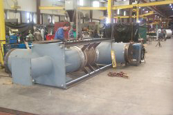
Expansion Joint Burst Testing to Determine Ultimate Pressure Resistance
The pressure rating is the maximum allowable pressure to be used for that particular expansion joint. Each pressure rating is specified on a case-by-case basis per expansion joint.
Expansion Joints Designed for a Pressure Rating of 150 PSIG at 176°F
It is the force generated due to the pressure inside the expansion joint. Pressure thrust is calculated by multiplying the area of the mean bellows diameter by the pressure.
How does US Bellows define a hydro-test pressure based on design pressure?
When engineers design fluid networks, a common question arises: Exactly what is a hydro test, and how do you determine the correct parameters?
A pipeline hydrotest ensures the structural integrity of the entire system before it enters active service. During this procedure, the piping is filled with liquid to apply hydrostatic water pressure against the internal walls of the entire system.
Industry standards require that the hydrostatic test pressure be calculated as a specific multiplier of the maximum design pressure, corrected for the temperature to ensure its operational integrity. The specific multiplier and correction factor will vary based on the piping design code.
Establishing the correct hydro test pressure validates the safety of welded joints and mechanical connections. This careful evaluation also applies to the pressure testing of valves to guarantee zero leakage under stress.
When determining the pressure for hydrostatic testing of your expansion joints, the most important aspect is the applicable design codes. Normally, the ASME SEC VIII Div.1 general hydro-test pressure will be 1.3 x design pressure, but if you are testing for ASME B31.1, B31.3,B31.4, it will be 1.5 x design pressure.
That being said, there are many other considerations that will determine the test pressure, such as: