Usbellows logo.png

EJMA Logo

US Bellows is a Standards Subscriber | Exp: Dec 31, 2026 | See ejma.org to check verification process
Celebrating over 20 years of EJMA membership

Root Cause Analysis of Expansion Joint Internal Sleeve Failure Under Reverse Flow Conditions

January 27, 2026

Front view liner

Overview and Background

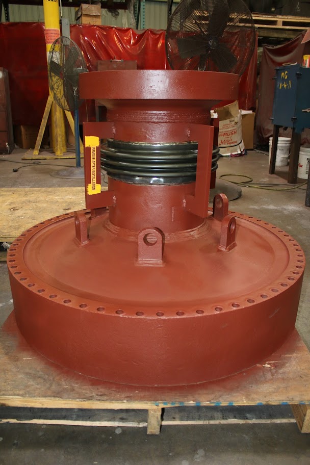
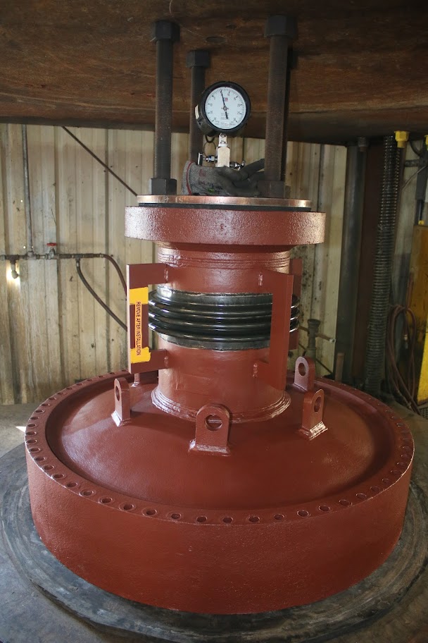
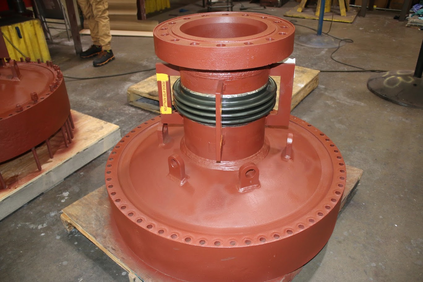
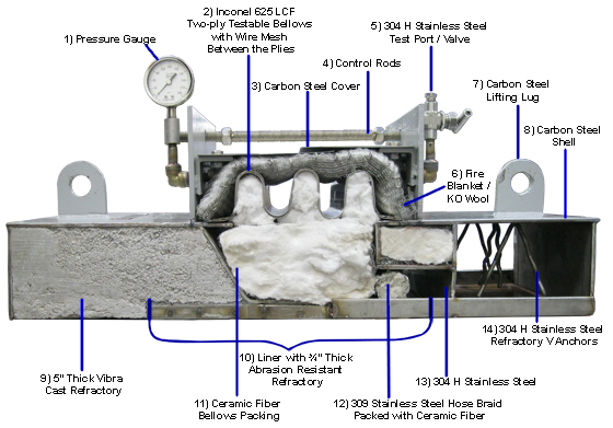
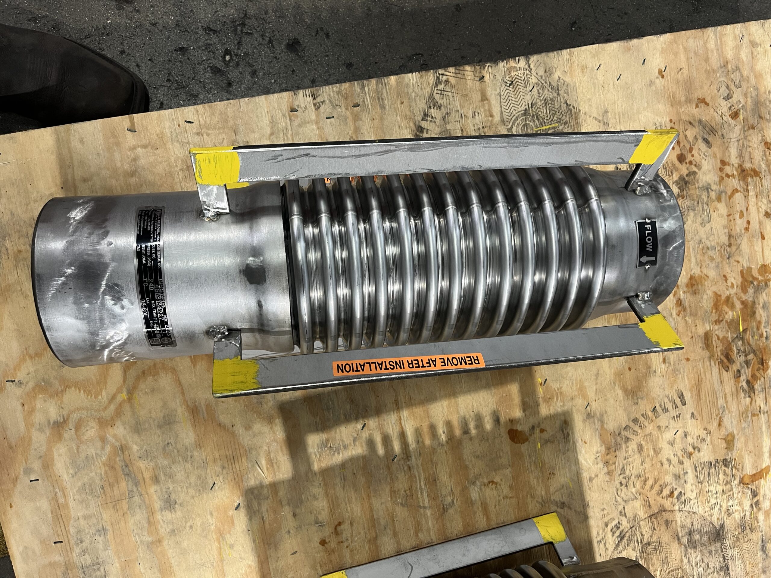
Expansion joints are crucial piping components designed to accommodate the flexibility requirements imposed by thermal expansion, vibration, and mechanical movement. In systems with high flow velocities, expansion joints often incorporate internal sleeves (flow liners) to protect the bellows convolutions by separating them from direct fluid flow and reducing the risk of flow-induced vibration (FIV).

The design of bellows expansion joints is generally governed by the guidelines set by the Expansion Joint Manufacturers Association (EJMA). However, current EJMA standards do not provide detailed guidance or design requirements for internal sleeves operating under reverse flow conditions.

Longitudinal slots in the sleeve are sometimes incorporated to equalize pressure between the inner and outer surfaces of the liner. However, care must be taken when designing these liners for reverse-flow conditions, as the slots act as a weak point in the design.

US Bellows was engaged by the end-user and conducted this case study after being asked to investigate several failures seen in the plant where the expansion joints were subjected to bidirectional flow conditions. Although an overseas company supplied the expansion joints, US Bellows agreed to conduct the analysis. 


Problem Description and Field Observations

Lng 1

The failure incident occurred at a Liquefied Natural Gas (LNG) facility with vacuum-jacketed lines. During transient operations, such as process upsets or startup/shutdown, the piping systems experience bidirectional.

  • Extent of Failure: Over 80 internal sleeves in the expansion joints showed some sort of deformation or buckling, and 10 liners had collapsed entirely.

The challenge that USB Faced was that the end-user did not want to change the design or replace all 80 expansion joints, as that would require extraordinary effort due to the expansion joints being installed in a double-walled system (vacuum jacket). The customer wanted to replace only the units that had collapsed entirely, and for us to determine a ‘safe-operating’ reverse-flow velocity to prevent further failures.

  • Failure Condition: Reverse flow speeds reached up to 40 ft/s when the field failures occurred.
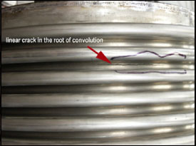
  • Mechanism Suspected: The core issue stemmed from the longitudinal pressure equalization slots. Under reverse flow, these slots can deform or close, preventing effective pressure equalization and, in turn, generating damaging forces that can accelerate liner deformation or collapse.

The liner design studied had an outer diameter of 8-¼”, a length of 25”, and 22 individual slots with an opening of 1/32.”

Methodology: Fluid Structure Interaction (FSI) Analysis

Liner no 2

To determine the root cause and a safe operating limit, the investigation employed a combination of Computational Fluid Dynamics (CFD) and Finite Element Analysis (FEA) using a one-way coupled Fluid Structure Interaction (FSI) methodology.

 CFD forces (fluid pressures) were generated and then mapped onto the FEA mesh to calculate resulting deformations. The analysis considered the non-linear relationship between large deformations, applied fluid pressures, and the subsequent closure of the pressure equalization slots.

The study analyzed three primary geometries reflecting different operational states and tolerances:

  1. “Gaps Open”: The as-manufactured, undeformed geometry.
  2. “Gaps Closed”: A deformed geometry reflecting the start of closure of the original slot open area.
  3. “Angled Liner”: A geometry simulating installation offset with a 1° angulation forced on the expansion joint.
  • Acceptance Criteria: Results were evaluated against ASME Section VIII Division 2 criteria for plastic collapse and local failure.

 Key Findings and Root Cause Determination

The FSI analysis confirmed the failure mechanism and established a safe operating limit:

A. Pressure Differential and Plastic Collapse

The study found that the limiting criterion was plastic collapse.

  • The pressure differential between the inner and outer sleeve surfaces significantly increased with flow speed, which was because this accelerated the closure of the slots in the liner. Pressure will not equalize effectively as the slots close. This pressure imbalance produced inward radial deformation.
  • Crucially, the “gaps closed” model generated a significantly larger pressure differential compared to the “gaps open” model at the same speeds. This result demonstrates that slot closure directly causes increased stress and deformation. In fact, it was found that an already deformed liner increases the pressure differential by a factor of 2. 
  • The root cause of failure was pressure-differential-induced plastic collapse triggered by the closure of the equalization slots during reverse flow. The deformation increases the differential pressure as the slots close, which in turn increases the force, which further increases deformation, potentially leading to an unstable cycle.

B. Determining the Failure Speed

  • The initial (“gaps open”) geometry passed the plastic collapse criterion until approximately 65 ft/s.
  • However, when iterating on the deformation (i.e., using the “gaps closed” model), the plastic collapse failure speed dropped sharply to approximately 38 ft/s.
  • This calculated failure speed of 38 ft/s aligned closely with the field observations, where complete collapse occurred near 40 ft/s.

C. Influence of Geometry and Turbulence

  • Asymmetry/Angulation: Geometric imperfections and installation tolerances were highly influential. The angled liner (1° angulation) case showed drastically higher resulting pressure differentials, suggesting that even small amounts of bellow angulation significantly increase generated forces.
  • Transient Effects: Simulations involving turbulent flow conditions (deadleg and mixing flow cases) showed that while forces varied over time, the variations were not at a resonant frequency or high enough magnitude to cause significant deflections. The study concluded that transient effects and turbulence were insignificant as the primary failure mechanism; the collapse was static in nature.
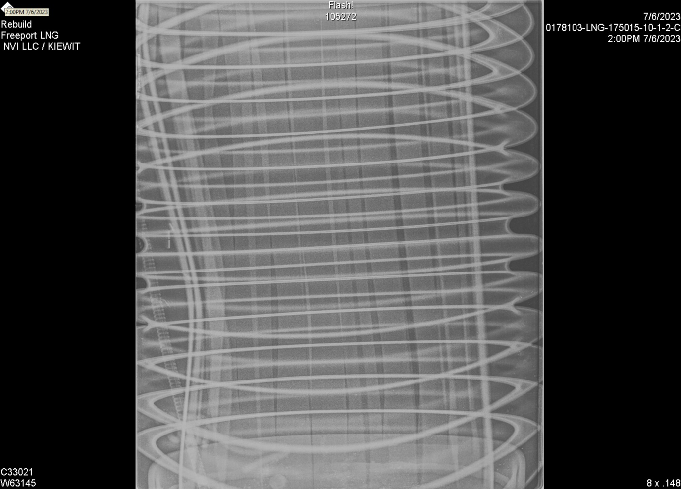
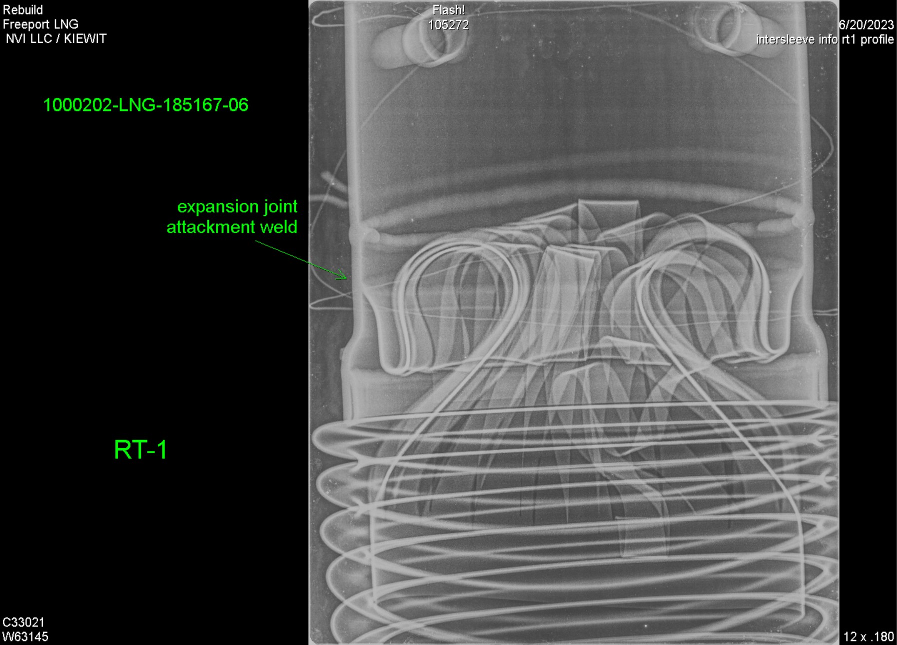
  • Field Validation: X-ray inspections of damaged liners in the facility confirmed deformation patterns and extreme plastic deformation consistent with the shapes and locations predicted by the simulation model.


Resolution and Recommendations

Top view liner

The study demonstrated a reliable methodology for qualifying expansion joint liners against reverse flow instability, providing guidance where EJMA standards currently lack detail. A one-way CFD–FEA coupling can effectively predict instability in expansion joint liners under reverse flow, especially when large deflections are involved, provided stability is proven through iterative deformation analysis. The design is considered acceptable if the radially inward deformation does not increase with subsequent iterations, indicating that stability is achieved at that flow speed.

Conclusion: The expansion joint liners failed due to plastic collapse driven by an excessive pressure differential resulting from the closure of pressure equalization slots at high reverse flow speeds (near 40 ft/s).

Our final report established a safe reverse-flow limit for the existing expansion joint design, allowing our client to operate safely as long as the flow velocity is not exceeded.

Finally, this study, its methodology, and its results were submitted and published for the ASME Pressure Vessels and Piping Conference.  

——————————————————————————–

An expansion joint internal sleeve is like a dam with controlled overflow gates. If the water flow suddenly reverses (reverse flow), the equalization gates (slots) might get pushed shut by the new pressure direction. If the gates close, the pressure differential across the dam wall (the sleeve) spikes dramatically, causing the entire structure to collapse or buckle because the pressure is no longer balanced.

Read More

Fatigue Testing or Cyclic Testing

November 5, 2025

Fatigue Testing

Fatiguetest 3
Fatigue Testing on a 12″ Bellow

Fatigue Testing PDF

This is a preliminary summary report describing fatigue testing conducted by U.S. Bellows, Inc. The objective of the fatigue test was to detect fatigue crack growth generated by compressions during controlled cycling on a fatigue-testing machine.

U.S. Bellows, Inc. conducted a fatigue test on 12” diameter A240 TP 321SS bellows with 8 convolutions. The EJMA calculations for this test was based on compressing the bellows 2.3/4” 1000 times. This bellows was attached to each side of the cylinder of the fatigue test machine and pressurized to 25 PSIG for the purpose of leak detection. This bellows failed in the root of the convolutions at 1,285 cycles.

Fatiguetest 2 Fatiguetest 3
Figure 1 shows an overall view of the axial cycle fatigue test machine with bellows installed Figure 2 shows a linear crack in the root of the convolution–about 3 inches long, which is typical of bellows low cycle fatigue)
This test has proven that U.S. Bellows Inc., EJMA cycle life calculation of 1,000 cycles is met. The actual cycle life of 1,285 cycles is higher than the EJMA Calculated cycle life.


Key reasons Cyclic Testing can be important in design and operational considerations: 

  1. Validates design life – Confirms the joint meets its rated cycle life as calculated per EJMA formulas.
  2. Ensures structural integrity – Verifies welds, convolutions, and materials won’t crack or fail under repeated flexing.
  3. Confirms design assumptions – Demonstrates that analytical or computer-based life predictions match real-world performance.
  4. Enhances safety and reliability – Prevents premature failure in high-pressure or high-temperature piping systems.
  5. Spring rate check – When coupled with a load cell, it can verify that the spring rate of the expansion joint matches or exceeds theoretical calculations. Doing this will verify the assumptions done in a Pipe Stress Analysis (PSA).


Read More

U.S Bellows Quick Turnaround Refurbishing Of Failed Bellows

November 29, 2022


Need it quickly? Here at PT&P our standard emergency orders is within
24 hours. Beyond our fast and custom quote turnaround and dependability
There are a number of ways we stand out in the industry, all wrapped around
two things: Our commitment to customers & our goal to provide a quality
product in a timely manner.

9/25/22

U.S Bellows receives 3 failed bellows from a petroleum plant in Louisiana

Img 3618 (1)

9/27/22

U.S Bellows begins by removing the failed bellows. Followed by cleaning and removing of rust and debris by sand blasting and coating the carbon steel with a shop primer to prevent future rusting.

Fullsizer 1
Img 7977 (1)

9/27/22

U.S Bellows fabricated new bellows formed using Inconel-625 material. The bellows long seams welds were radiograph tested(RT). The bellows attachment welds to the floating head heat exchanger were Liquid penetrant examined, and the completed assemblies were air and soap leak tested.

Img 7975 (1)
Img 7970

9/27/22

After completing the 100% X-rayed and air leak examination. The Bellows calculations done by our engineer and the refurbished expansion joint were all reviewed by an ASME Authorized inspector (AI) verifying compliance to ASME Section VIII design code and signed off on the ASME report.

Img 7973


9/29/22

Once the units were completed U.S Bellows made shipping arrangements and the refurbished units were received at the jobsite within 2 hours after shipment.

Image8


Read More

Fabric Expansion Joint Diagrams

August 2, 2019

Standard Fabric Expansion Joint

High Temperature 3-Layer Expansion Joint


Request a Quote


Read More

Refractory Lined Expansion Joint Diagram

  1. Pressure Gauge – to monitor the pressure between the plies
  2. Inconel 625 LCF Two-ply Testable Bellows with Wire Mesh between the Plies – the wire mesh ensures flow from one side to the other side across the convolutions
  3. Carbon Steel Cover – pressure sealing in the even of bellows leak
  4. Control Rods – limits thermal movement
  5. 304 Stainless Steel Test Port / Valve – connection for air test of bellows
  6. Fire Blanket / KO Wool – keeps the bellows temperature above the dew point temperature of the flue gas (350°F to 450°F)
  7. Carbon Steel Lifting Lug – facilitates lifting
  8. Carbon Steel Shell
  9. 5″ Thick Vibra Cast Refractory – reduces shell temperature to 350°F
  10. 3/8″ Thick 304 Stainless Steel Liner with 3/4″ Thick Abrasion Resistant Refractory
  11. Ceramic Fiber Bellows Packing – reduces bellows temperature to under 1000°F
  12. 309 Stainless Steel Hose Braid Packed with Ceramic Fiber – seals the liner gap to prevent the catalyst from collecting in the bellows
  13. 304 H Stainless Steel – insulation box
  14. 304 H Stainless Steel Refractory V Anchors – secures refractory to pipe
Read More

Tension Systems

May 21, 2019

In some cases, a straight line system of axial bellows anchors and guides is not practical or desired; or there is no reasonable way or place to anchor the bellows thrust loads. In such cases self restrained bellows assemblies may be used, such as the double hinge restrained bellows shown below. Thermal expansion (or contraction) in the long pipe is absorbed by an offset deflection of the double hinge assembly.

Bellows thrust load is carried by hinge bars, gimbals, tie rods or other such devices; hence normal tension is maintained in the pipe system and main anchors and full lateral restraint guides are unnecessary. See Reference1 for more information.

Reference2: W. Flügge, “Stresses in Shells”, p 434-436, Springer-Verlag, Berlin/Göttingen/Heidelberg, 1962

Read More

Intermediate Anchors & Pipe Guides and Pipe Buckling 

May 9, 2019

Bellows Expansion Joint: Pressure Loads, Anchors & Guides

Appendix

Intermediate Anchors & Pipe Guides and Pipe Buckling

Pipe systems containing bellows and external main anchors (compression system) must be guided by full lateral restraint type guides. No more than one bellows should be used between any two anchors. Hence if more than one bellows is required, the piping system should be divided up into sections, containing one bellows each, by intermediate anchors. Intermediate anchors do not carry pressure thrust load, but must be designed for bellows deflection forces and frictional forces from supports and guides. See “Tension & Compression System” for more information on this subject.

There are several important reasons for the requirement for guides:

1. Direct motion into the bellows.
2. Stabilize the ends of the bellows against “squirm.”
3. Prevent buckling of the pipe due to pressurized fluid column effect.
4. Weight support.

Rules for guiding of pipe containing bellows are given in “Tension & Compression System.”

Buckling of pipe due to the compression effects of a pressurized fluid column is not a widely understood phenomenon. In a tension system, where normal longitudinal tensile load is maintained, this cannot happen, no matter how long the un-supported (or guided) length of pipe. However, in a compression system a column buckling effect can occur, even when there is no externally generated longitudinal compression load on the pipe. Normally, with a bellows there is a longitudinal compression in the pressurized pipe due to bellows sidewall load. However it is the full bellows thrust area which determines the buckling pressure.

Consider the following arrangement:

Bellow6

A pipe with ends sealed, but not restrained is filled with fluid and subjected to internal fluid pressure by means of a hydraulic cylinder and piston at each end. At a certain critical compressive force “Fcr” and corresponding internal fluid pressure “Pcr” the pipe will buckle. Guides are required, therefore, to prevent such buckling.
In the above situation, the pressurized column of fluid is inherently unstable and depends on the flexural rigidity of the pipe for its stability.

Let E = Modulus of elasticity of pipe: psi
I = Moment of inertia of pipe: in 4
L = Length of pipe between guides: in.
Ae = Bellows effective thrust area: in 2
Substituting into Euler’s column formula for a pivot ended column:
Fcr = Fcr
But, Fcr = Pcr Ae
Therefore, critical buckling pressure Critical buckling pressure

A mathematical treatise of this subject and additional explanation is contained in “Reference ‘PA’ Load.”

Need another set of eyes on your project’s math? Get in contact with our engineer for guidance.

Read More

Main Anchor Design

May 8, 2019

Bellows Expansion Joint: Pressure Loads, Anchors & Guides

Appendix


Main Anchor Design

Bellows TID Fluid Area:

It seems reasonably apparent that in a system with a bellows the pipe internal fluid pressure load is not balanced y pipe longitudinal tensile forces and must be restrained by external forces. It can also be seen that if the bellows ID exceeds the pipe ID, an additional pressure force will be transmitted through the pipe as a compression load which must also be externally restrained. Hence one component of the total bellows thrust load is based on the bellows ID.

Bellows ID Area = Bull 03 a

Corrugation Sidewall Thrust:
It can also be visualized that internal pressure acting on the sidewall of the corrugation would tend to spread the corrugation out in the longitudinal direction, and this load must be restrained by an external reaction force. As an approximation consider a 1″ wide radial strip cut out of a corrugation.

Bull 03 b

For a fixed ended beam with uniform load, RID = ROD = Bull 03 c

Hence one half of the corrugation sidewall load is carried in tension at the crest of the corrugation. The other half it transmitted through the neck of the corrugation as a compressive force. This force must be resisted by the external main anchors and results in a (generally) small longitudinal compressive stress in the pipe.

Sidewall Effective Area =Bull 03 d

But ID + h = mean dia. = Dm

Therefore, Sidewall Effective Area =Bull 03 e

Total Effective Thrust Area:

Ae=ID area + Sidewall area

Ae=Bull 03 f

A more precise development of corrugation sidewall load and an equation for bellows effective thrust area is given in the Appendix. A comparison on 5 sample problems of typical bellows dimensions, including one extreme case of OD/ID ratio, shows that the percent error involved in using the mean diameter approximation is generally less than 1% and only 1 1/2% in the extreme example.

Read More

Bellows Expansion Joint Loads

April 25, 2019

Bellows Expansion Joint: Pressure Loads, Anchors & Guides

Pressure generated loads in piping systems containing bellows are sometimes not understood.  This can lead to system failures sometimes resulting in bellows failure and possible rupture even though the bellows design is adequate for the operating conditions.  The purpose of this paper is to examine the bellows loads imposed on piping system and to show some methods for dealing with these loads.

Bellows Expansion Joint: Pressure Loads, Anchors & Guides

Appendix

Read More

High Temperature Furnace Seal Bag

Us bellows high temperature furnace seal bag (2)

High-Temperature Furnace Seal Bags: A Cost-Effective Solution

US Bellows’ high-temperature furnace seal bags offer an economical solution to industrial heat loss. These specialized products create a flexible, airtight seal where pipes enter the furnace floor, minimizing heat escape.

By conserving heat, the seal bags improve the efficiency of the furnace system and cut operational costs. Employing a furnace seal bag enables the pipe to move through the furnace floor while maintaining an airtight seal to prevent excessive heat loss.

Prevent Heat Loss and Save Energy with Furnace Seal Bags

Gaps between the furnace floor and the pipe entry points can lead to considerable heat loss in specific furnace application scenarios. Similar to fabric expansion joints, furnace seal bags use multiple layers of flexible, heat-resistant fabric to manage thermal expansion. This design creates an airtight seal, preventing hot gas and energy loss, which improves the efficiency of the furnace system.

Key Features of US Bellows’ Furnace Seal Bags

US Bellows’ durable furnace seal bags feature an internal tapered steel coil to prevent collapse. Secured with stainless steel clamps or band straps, their durable design provides an easily replaceable and long-lasting thermal seal. 

Spaces between the furnace base and the pipe entry areas can result in heat energy loss in certain furnace uses. Our bag is crafted with multiple layers of flexible fabric that withstands both fire and high temperatures, making it ideal for harsh conditions. It adapts to changing furnace temperatures by expanding and contracting.

Our bag is composed of several layers of flexible, flame-retardant, and heat-resistant fabric, specifically designed to function in high-temperature environments. It adjusts by contracting and expanding in response to changing furnace temperatures. This sealing bag conserves energy and lowers expenses.

Don’t Let Energy Go to Waste. Get a Custom Furnace Seal Bag Quote.

Read More