

Usbellows logo.png

EJMA Logo

US Bellows is a Standards Subscriber | Exp: Dec 31, 2026 | See ejma.org to check verification process
Celebrating over 20 years of EJMA membership
Case Study: Delivering 200+ Expansion Joints in Record Time for a Large-Scale Battery Manufacturing Facility

April 29, 2026
Read Case Study

Request A Quote

Contact Us

Background

As global demand for battery production continues to accelerate, a major manufacturing facility undertook the development of a large-scale plant spanning two production buildings, requiring a highly coordinated piping infrastructure across multiple utility systems. These systems included chilled water, steam, nitrogen, compressed air, and condensate, all of which demanded precise engineering to ensure long-term reliability.

Due to the facility’s scale and complexity, piping systems needed to accommodate thermal expansion, lateral movement, and seismic activity, all within limited space and under an aggressive construction timeline. To meet these demands, Piping Technology & Products and its subsidiary, US Bellows, were selected to provide a fully integrated expansion joint and pipe support solution.

The Challenge

Initial piping designs relied on traditional solutions such as pipe loops and flexible hose assemblies. However, these approaches introduced significant limitations:

  • Limited Space Availability
    Large pipe loops were impractical in congested mechanical corridors and overhead routing areas, restricting design flexibility.
  • Complex Movement Requirements
    The system needed to absorb multi-directional movement—including axial, lateral, and seismic displacement—without compromising performance.
  • Fragmented Procurement Strategy
    Using multiple vendors for expansion joints, supports, and analysis increased coordination challenges and project risk.
  • Aggressive Schedule Constraints
    Long lead times and decentralized sourcing threatened to delay construction and impact overall project delivery.

The project required a more compact, efficient, and fully engineered solution that could address movement requirements while simplifying both procurement and installation.


The Engineered Solution

Diagram

To overcome these challenges, US Bellows developed a custom nested Super U-Loop configuration using metallic expansion joints, replacing traditional pipe loop designs.

As illustrated in the engineering layout diagram on page 2, the nested configuration allows multiple expansion joints to work together within a compact footprint, effectively absorbing movement without requiring large spatial allowances.

This approach provided several advantages:

  • Efficient absorption of thermal and lateral movement within constrained spaces
  • Improved system reliability compared to flexible hose designs
  • Reduced footprint, enabling installation in tight routing environments

Integrated Engineering Approach

Piping Technology delivered a single-source solution, combining multiple components into one coordinated system:

  • Metallic expansion joints
  • Pipe expansion U-loops
  • Engineered pipe supports
  • Guides and anchors
  • Comprehensive pipe stress analysis

This integrated model significantly reduced interface risk while improving design coordination and execution efficiency.

Close collaboration between engineering teams, contractors, and field personnel ensured that all designs aligned with real-world installation conditions, minimizing delays and rework.


Advanced Engineering & Design Features

Image033

The solution was supported by detailed pipe stress analysis, validating performance under thermal, pressure, and seismic loading conditions. Key design elements included:

  • Nested expansion joint configuration for multi-directional movement
  • Flow liners to protect against turbulence and internal wear
  • Protective covers to enhance durability and extend service life
  • Custom supports and guides to control movement and maintain system integrity
  • PE-stamped calculations and drawings for full engineering validation

This level of engineering ensured both fit within tight layouts and reliable long-term performance across all operating conditions.


Field Support & Responsiveness

Following installation, minor field constraints were identified that limited the movement of certain expansion joints.

US Bellows and Piping Technology responded rapidly by:

  • Evaluating on-site conditions
  • Providing updated engineering recommendations
  • Supporting field adjustments to restore proper functionality

This proactive response minimized operational disruption and ensured the system performed as intended without major rework.


Results

Image016

The project demonstrated the combined strength of engineering expertise and manufacturing capability:

Engineered Performance

  • Successfully accommodated thermal, lateral, and seismic movement
  • Eliminated the need for large, space-consuming pipe loops
  • Delivered a more reliable and maintainable piping solution

Manufacturing & Execution

  • Supplied 200+ expansion joints ranging from 4” to 36”
  • Delivered over 400 product configurations and 6,000+ total units
  • Completed 69 coordinated shipments to match construction sequencing
  • Executed the entire scope within approximately five months

Project Value

  • Simplified procurement through a single-source solution
  • Improved installation efficiency and reduced field modifications
  • Supported aggressive construction timelines with responsive delivery

Conclusion

By replacing traditional pipe loop designs with a compact, engineered Super U-Loop expansion joint solution, Piping Technology & Products and US Bellows delivered a high-performance system tailored to the demands of modern battery manufacturing facilities.

The project highlights the value of integrated engineering, innovative design, and responsive execution, enabling complex industrial projects to meet tight schedules without compromising reliability or performance.

Read More

Clamshell Bellows Replacement for a Heat Exchanger Expansion Joint

April 24, 2019

By John Demusz

June 24, 2010

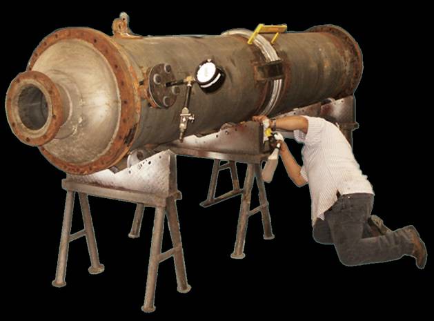
Most fixed tube heat exchangers have an expansion joint on the shell side of the exchanger. The shell side expansion joint compensates for the differential thermal growth between the tube and the shell under operating conditions. If the expansion joint would start to leak, it can cause serious operational and safety issues. Replacing a bellows in a heat exchanger is viewed as an extremely expensive process since the tubes must be removed from the tube sheet to replace the bellows.

US Bellows can retrofit your heat exchanger bellows without removing the tubes from the tube sheet. Our “clam shell technology” enables US bellows to remove the existing leaking bellows and replace it by installing a clam shell bellows. The clam shell bellows is fabricated by removing the existing bellows and obtaining precise dimensions to correctly fabricate a new bellows. The new bellows will be formed to the exact dimensions of the heat exchanger then cut into two pieces. Both halves of the bellow will be installed on the exchanger by welding the two halves together. The longitudinal bellows welds will be dye-penetrant examined for quality assurance. The new bellows replacement can also be hydro-tested in our facility.

US Bellows/Sweco Fab. Maintain ASME code U Stamp and R stamp which are renewed every three years. Materials or construction meet our customer’s specific requirements for all types of media, pressure, and temperature conditions. Clam shell bellows can save thousands of dollars.

Read More

85″ Dia. Clamshell Spools Designed for an Exhaust Wall Protrusion Clamshell at a Gas Turbine Facility

April 4, 2016

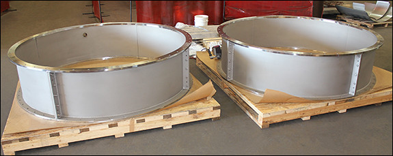
85” Dia. Clamshell Spools Designed for an Exhaust Wall Protrusion Clamshell at a Gas Turbine Facility

These clamshell pipe spools were fabricated by U.S. Bellows for a section of the duct for a gas turbine installation. The units were constructed from ASTM A.240 type 321 stainless steel. The flanges had a 32 RMS machined faces for bolting up the flanges without gaskets. The spools were designed to be removed in four sections so that the spool could be removed and the turbine pulled back for maintenance. They are 85.5″ in diameter and 21.5″ in overall length. The units were designed for an operating temperature ranging from -40°F to 950°F.

Read More

Clamshell Bellows for a Shell and Tube Heat Exchange

August 9, 2002
Clam Shell Bellows for a Shell and Tube Heat Exchanger
Clam shell bellows for a shell and tube heat exchanger.

US Bellows fabricated and installed a clamshell bellows for a shell and tube heat exchanger. The clamshell bellows are designed and fabricated per ASME VIII Div. 1 Appendix 26. It has a 14″ diameter and was designed at 150ºF and 150 PSIG. In order to detect any leaks, prior to and following forming, the heat exchanger and its welds were subjected to a series of tests, including a 100% dye-penetrant, x-ray, and air test.

Read More