

Expansion joints solve an important engineering problem: they accommodate thermal movement without requiring a large pipe loop. That flexibility comes with a defined operating envelope. When pressure exceeds the approved limit, a component designed to protect the piping system can become a point of failure.
A reported incident at a refinery in South Texas makes that distinction clear.
The Incident at a Glance
| Item | Details |
| Event | Pressure test during a turnaround |
| Equipment | Heat exchanger with an expansion joint incorporating a 4-inch Inconel 625 Grade 1 bellows |
| Bellows design pressure | 300 psi |
| Pressure applied | 1,500 psi, five times the stated design pressure of the bellows |
| Other heat exchanger components | Rated for 1,500 psi |
| Result | The bellows failed and had to be replaced on an emergency basis |
The Failed Joint: A Visible Warning
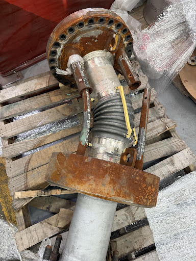
The failed assembly in the first photo shows pronounced distortion of the bellows convolutions. Instead of keeping their regular geometry, the convolutions appear displaced and deformed. The photograph shows damage following the reported overpressure event, but it cannot, by itself, establish the precise failure mechanism.
How the Repair Went
- US Bellows was contacted on a Sunday morning.
- The failed assembly was dropped off at noon.
- The unit was refurbished and re-tested at the correct pressure within 3 working days.
- The unit came back with the proper ASME documentation, because it forms part of an ASME-coded heat exchanger.
Why a Strong Alloy Can Still Fail
Inconel 625 is valued for its strength and corrosion resistance, but the alloy alone does not determine bellows performance. The thin, formed convolutions that make movement possible also require careful evaluation of thickness, geometry, temperature, pressure stability, and fatigue life.
Excessive pressure can cause:
- Permanent deformation of the convolutions.
- Squirm: an instability in which the bellows bows sideways under internal pressure.
- Rupture of the bellows.
- Higher pressure thrust: more load on the engineered anchors or restraints.
System over-pressure, in service or during hydrotest, is also listed among the causes of expansion joint failure. These are potential failure mechanisms. Identifying the mechanism in this incident requires a qualified investigation.
The safety consequences extend beyond a damaged joint:
- Loss of containment: pressurized fluid can escape suddenly and violently.
- Stored-energy release: rupture can produce dangerous movement or flying components.
- Fire or explosion: a flammable release can ignite, depending on the fluid and surrounding conditions.
- Personnel and plant exposure: serious injuries, fatalities, equipment damage, and extended shutdowns are possible.
The Replacement: New Hardware, Same Need for Pressure Control
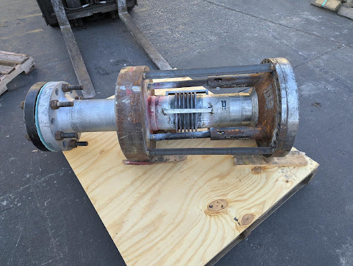
The replacement assembly in the second photo has more uniform bellows convolutions. That is a useful visual contrast, not evidence that the replacement can withstand 1,500 psi. Verify its approved rating from the manufacturer’s documentation, such as the ASME U-2A Partial Data Report, if that report is not readily available.
Five Precautions That Keep Flexibility From Becoming a Failure Point
1. Know the Limit Before Applying Pressure
- Verify the approved pressure and temperature limits for the bellows and the complete assembly, including movement conditions and any external-pressure requirements.
- Review the nameplate, datasheet, and manufacturer’s instructions.
- Never use the flange rating as a substitute for the bellows rating.
- If unsure, check with the manufacturer.
2. Treat Pressure Testing as a Separate Engineering Decision
- Do not assume the piping system’s hydrotest pressure is acceptable for an installed expansion joint.
- US Bellows’ installation instructions say not to exceed a pressure test of 1-1/2 times the rated working pressure.
- Obtain a written, manufacturer-reviewed test procedure and an authorized test pressure.
- If necessary, isolate or remove the joint using an engineered arrangement before testing the rest of the system.
3. Pressurize Gradually and Manage Stored Energy
- Use calibrated gauges and transmitters with appropriate ranges and locations, and confirm the measurement represents pressure at the joint.
- Follow approved pressure stages, hold points, and stop criteria.
- Vent trapped air during hydrotesting, as specified in the procedure.
- Pneumatic testing requires a specific engineered safety assessment. Compressed gas stores substantially more energy than a liquid-filled system at the same pressure.
4. Verify the Pressure-Thrust Load Path
- Confirm that anchors, guides, tie rods, and other restraints match the approved design and are in serviceable condition.
- Do not pressure test before all guides and anchors are installed.
- Do not assume shipping bars are permanent pressure restraints, or that tie rods can accommodate unlimited pressure.
- Never adjust or remove restraint componen
5. Keep People Outside the Hazard Zone
- Establish barriers and an exclusion zone appropriate to the test or operating risk.
- Use remote pressurization and monitoring where practical.
- Consider escaping fluid, rupture direction, and moving components.
- Personal protective equipment supplements these measures. It does not make proximity to an overpressurized joint safe.
The Drawing Is a Reference, Not a Shortcut
Heat exchanger assembly drawings help explain component arrangements, but the drawing alone does not establish the bellows operating and test limits.
- A certain flange rating on the assembly does not mean every component is rated for that pressure.
- Confirm the complete approved design and test documentation before applying pressure.
Before the Next Test, Ask One Question
Have we verified the pressure limit of every component in this test boundary, not just the pipe?
If the answer is uncertain, stop and resolve it before pressurization. The safest replacement strategy is not simply installing another joint. It is preventing the same pressure exposure from reaching it again.
Related Work
- Quick turnaround refurbishing of failed bellows on a floating head heat exchanger.
Unsure About a Pressure Limit?
For help reviewing expansion joint pressure, movement, and installation requirements, schedule time with a US Bellows engineer. For a replacement or new application, request a quote.
Upcoming Live Webinar
Sign-up for a Live Technical Webinar…
U.S. Bellows 101 - The Basics of Expansion Joints
Date: Thursday, November 12, 2026 - Register for 10:00 am OR 2:00 pm
*Note: Time Zone is CDT * Central Daylight Savings Time / GMT -5h
Live Webinars are 1 PE/PDH Credit for TX Professional Engineers
Listen to in-depth explanations on how to choose the type of expansion joint that will best suit your system. Learn about the bellows movements throughout the piping system due to thermal changes of mechanical motion. Increase your understanding of the different types of expansion joints and value-added services offered by U.S. Bellows.
Upcoming Webinars:
November 19th: Pipe Support Field Inspection, Installation and Maintenance Webinar 10:00 am OR 2:00 pm
December 3rd: U.S. Bellows - Expansion Joints In-depth Webinar 10:00 am OR 2:00 pm
December 10th: Constant Spring Supports Design and Application Webinar 10:00 am OR 2:00 pm
View video recordings from past webinars…
Online Course
Expansion Joint Application and Design
Our Expansion Joint course was developed for the following disciplines…
- Piping system designers that may decide to use expansion joints
- Expansion joint designers use the information provided by piping system designers to determine the best design to meet the requirements.
- Designers that use modern software systems to evaluate different options
- Engineers / Managers: field, maintenance, process, operations, construction, surveyors
*This online course is approved for 8 hrs. P.E. Credits
Register Now