Designing safe piping systems requires a clear understanding of internal pressure dynamics. The effective area of a metallic bellows is the cross-sectional surface area over which internal fluid pressure exerts an outward force.
Engineers rely on this physical metric when calculating thrust force to determine the exact mechanical load placed on the piping equipment or anchors supports.
Once this pressure thrust is identified, facilities can properly size main pipe anchors or select self-restraining expansion joints to handle the load.
This precise analytical approach guarantees the pipeline’s structural integrity under maximum stress.
Understanding Pressure Thrust Forces and Why Proper Anchor Design Matters
Bellows Effective Thrust Area: Explained
Calculating the effective thrust area (Ae) of a bellows in a piping system is crucial to determine the external anchor forces required to restrain it.
When a pipeline without a bellows is pressurized, the forces created by the pressurized internal fluid are balanced by the pipe tension.
However, when a bellows is pressurized, the internal fluid pressure creates forces that push longitudinally along the pipe and bellows. These forces are no longer balanced by pipe tension, and the bellows will stretch due to this force, so you must use external anchors or restraints on the expansion joint to hold everything in place. The total force you need to restrain has many names in the industry: Expansion joint pressure thrust, bellows restraining force or bellows effective thrust.
Understanding the effective thrust area of a bellows ensures the proper design and installation of your expansion joint.
Two Main Components of Thrust
Calculating the bellows effective thrust area involves considering all contributing factors where internal pressure can exert a longitudinal force. Fundamentally, this area is comprised of two main components:
2. Bellows Internal Diameter (ID) Fluid Area
If the bellows ID is larger than the pipe ID, the internal pressure acts on a larger cross‑sectional area, generating greater thrust than the pipe alone would produce. Because the pipe’s tensile strength does not naturally counteract this thrust, it must be restrained by main anchors.
The fluid thrust force from the bellows bore can be calculated as:
![]()
2. Corrugation Sidewall Thrust
Internal pressure also acts on the sidewalls of the corrugations. This pressure tends to spread the corrugations apart in the longitudinal direction. To visualize this, imagine cutting a 1-inch-wide radial strip from a corrugation and observing the forces acting on it.
While the ID area accounts for most of the thrust, the sidewall corrugations also contribute. Even though this component is usually smaller, it still adds to the total force that must be restrained.
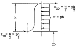
For a fixed‑ended beam with uniform load, the reaction forces at the inner and outer diameters of the bellows are:
RID = ROD =  Where: p = internal pressure and h = corrugation height
How the load is carried
- Half of this sidewall load is carried in tension at the crest of the corrugation.
- The other half travels as a compression force through the corrugation neck into the pipe wall.
This compression force must be resisted by the main anchors, producing a small longitudinal compressive stress in the pipe.
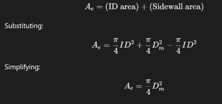
3. Sidewall Effective Area
We can estimate the sidewall’s contribution to thrust by calculating the difference between two circular areas:
Sidewall Effective Area =![]()
Since: ID + h = Dm (mean diameter)
This becomes: Sidewall Effective Area =![]()
4. Total Effective Thrust Area
The total effective thrust area is the sum of:
1. Bellows ID area (bore thrust)
2. Sidewall effective area (sidewall thrust)
For practical calculations, a common and often accurate approximation for Ae uses the mean diameter (Dm) of the bellows. In fact, EJMA uses the simplified version for the design equations for metallic bellows.
A precise development of the corrugation sidewall load, along with a more exact equation for Ae, can be found in detailed engineering appendices on this page, but the mean diameter approximation offers a strong foundation for most design considerations.
Understanding the effective thrust area ensures you design anchors and guides that maintain system stability and reliability. For detailed engineering support or to discuss your project requirements, connect with our team below.
Did you know that US Bellows is a Piping Technology Company?
We are proud to be a one-stop solution from expansion joints to pipe supports and engineering services. We work hard to simplify your supply chain, and ensure system reliability with quality assurance.
Bellows Expansion Joint Resources for Pressure Loads, Anchors & Guides
- Tension & Compression System
- Bellows “PA” Load
- Bellows Effective Thrust Area
- Main Anchor Design
- Intermediate Anchors, Pipe Guides and Pipe Buckling
- Tension Systems
Appendix