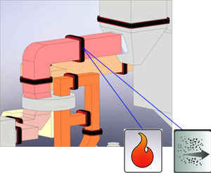
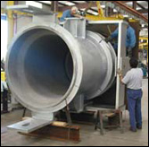
High Temperature Dirty Flue Gas Expansion Joint Applications
Similar Applications
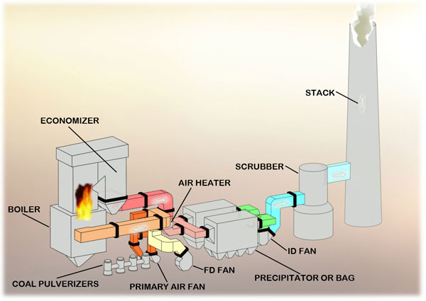
Fossil Fired Power Plant, Gas Recirculation System, Pulp and Paper Plant, Recovery Boiler to Precipitator, Refinery Turbo-Expander to CO Boiler and CO Boiler to Precipitator, Cement Plant, Clinker Cooler to Heat Exchanger
Typical Conditions
650°F to 850° operating temperature, -10" to -25" WG pressure, Fuel gas media with heavy particulate, Boiler growth contributes to large axial or lateral expansion joint movements depending on the orientation of the joints.
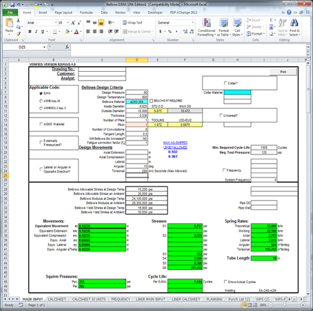
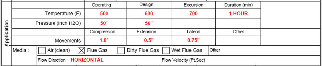
Sample Data Sheet for Listed Applications
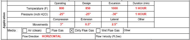
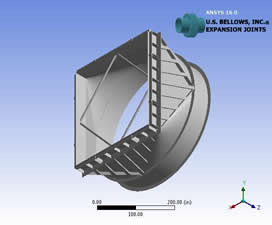
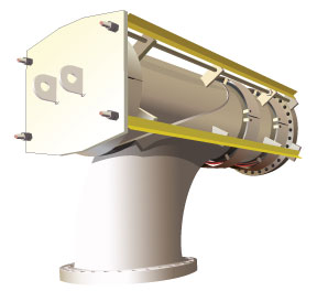
Recommended Expansion Joint Designs
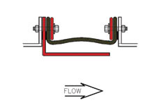
Common Design Features:
- Fabric Belt: Un-insulated fabric material. (FLEXXCEL HD7)
- Accumulation barrier: Fills expansion joint cavity to minimize the accumulation of particulate.
- Liner: Flow liner to retain the accumulation barrier and protect the belt from abrasion
Style 200W
 |
- Design Performance: *****
- Manufacturing Cost: $$$
- Installation Cost: $$
|
Unique design features: Integral telescoping liners to retain the accumulation barrier and protect the belt from abrasion.
Style 100W
 |
- Design Performance: ****
- Manufacturing Cost: $$
- Installation Cost: $$$
|
Unique design features: Field weld liner.
Style 300W
 |
- Design Performance: ****
- Manufacturing Cost: $$$$
- Installation Cost: $$$
|
Unique design features: Integral liner.
Style 600W
 |
- Design Performance: **
- Manufacturing Cost: $$$$
- Installation Cost: $$$$
|
Unique design features: Field weld liner, Ease of pre-compression for installing in breech opening, Requires belt attachment nuts to be tack welded, Leakage around belt attachment fasteners possible.
Style 700W
 |
- Design Performance: ***
- Manufacturing Cost: $$$
- Installation Cost: $$$
|
Unique design features: Belt installed and replaced from inside the duct, Field weld liner, Ease of pre-compression for installing in breech opening, Requires belt attachment nuts to be tack welded, Leakage around belt attachment fasteners possible.
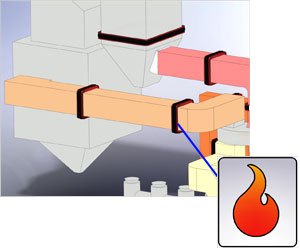
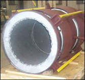
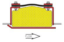
High Temperature Clean Air Expansion Joint Applications
Similar Applications
Fossil Fired Power Plant, Air Heater to Coal Pulverizers, Cement, Clinker Cooler to Heat Exchanger
Typical Conditions
600°F to 750° operating temperature, 5" to 80" WG pressure, Clean air media, Boiler growth contributes to large axial or lateral expansion joint movements depending on the orientation of the joints.
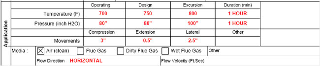
Sample Data Sheet for Listed Applications
Recommended Expansion Joint Designs
Common Design Features:
- Fabric Belt: High temperature fabric belt. (FLEXXCEL HT1, HT3, or HT5 depending on maximum temperature.)
- Standoff: 6" minimum standoff and outboard belt attachment flanges to dissipate heat.
- External duct insulation: contoured around expansion joint to allow heat dissipation. (See page xx for details.)
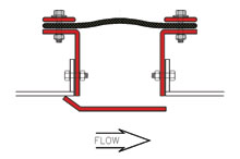
Style 200W
|
- Design Performance: *****
- Manufacturing Cost: $$$
- Installation Cost: $$
|
Unique design features: Field weld frame to duct. Integral telescoping liners to increase fabric material life.
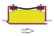
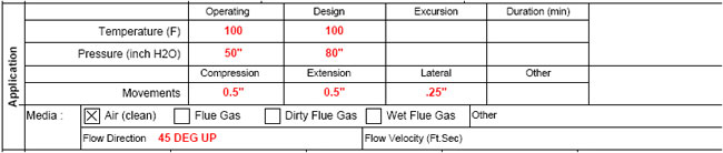
Style 100W
|
- Design Performance: ****
- Manufacturing Cost: $$
- Installation Cost: $$$
|
Unique design features: Field weld frame to duct. Field weld liner to increase fabric material life.
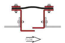
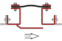
Style 300W
|
- Design Performance: ****
- Manufacturing Cost: $$$$
- Installation Cost: $$$
|
Unique design features: Field weld frame to duct. Integral liner to increase fabric material life. Designed for large breech openings
Style 200B
 |
- Design Performance: *****
- Manufacturing Cost: $$$$
- Installation Cost: $$$$
|
Unique design features: Integral telescoping liners to increase fabric material life. Bolt in design for attachment to equipment or duct flanges. Does require tacking welding nuts. Critical information required to insure proper fit-up.
Style 100B
 |
- Design Performance: ****
- Manufacturing Cost: $$$
- Installation Cost: $$$$$
|
Unique design features: Field weld liner to increase fabric material life. Bolt in design for attachment to equipment or duct flanges. Does require tack welding nuts. Critical information required to insure proper fit-up.
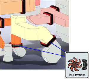
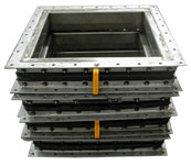
Turbulent Air Expansion Joint Applications
Similar Applications
Pulp and Paper Plant, Primary Air to Recovery Boiler
Typical Conditions
Ambient temperature, 40" to 50" WG pressure, Clean air Movement mainly limited to vibrations
Sample Data Sheet for Listed Applications
Recommended Expansion Joint Designs
Common Design Features:
- Fabric Belt: At fan locations, a flutter resistant fabric belt material should be used. (FLEXXCEL FF1)
- Standoff: Bolt-in design for attachment to equipment or duct flanges.
- External duct insulation: Flow liner to reduce turbulence/flutter of fabric belt material.
Style 200B
|
- Design Performance: *****
- Manufacturing Cost: $$$$
- Installation Cost: $$$$
|
Unique design features: Integral telescoping liners. Does not require tack welding nuts.
Style 100B
|
- Design Performance: ****
- Manufacturing Cost: $$$
- Installation Cost: $$$$$
|
Unique design features: Field weld liner. Does not require tack welding nuts.
Style 300B
 |
- Design Performance: ****
- Manufacturing Cost: $$$$
- Installation Cost: $$$
|
Unique design features: Integral liner. Ease of pre-compression for installing in breech opening.
Style 400B
 |
- Design Performance: ***
- Manufacturing Cost: $$$
- Installation Cost: $$$
|
Unique design features: Integral liner. Ease of pre-compression for installing in breech opening. Requires belt attachment nuts to be tack welded.
Style 500B
 |
- Design Performance: ***
- Manufacturing Cost: $$$
- Installation Cost: $$$
|
Unique design features: Bolt-on liner. Flanges on fabric belt attach directly to duct flange or equipment.
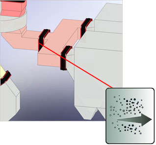
Dirty Flue Gas Expansion Joint Applications
Similar Applications
Cement Plant, Preheat Tower, Refinery, CO Boiler to Precipitator
Typical Conditions
250° F to 500° operating temperature, -35" to -50" WG pressure, Flue gas with possibly fly ash carryover through air heater, Moderate thermal movements in ducting.
Sample Data Sheet for Listed Applications
Recommended Expansion Joint Designs
Common Design Features:
- Fabric Belt: Un-insulated fabric material. (FLEXXCEL HD7)
- Accumulation barrier: Fills expansion joint cavity to minimize the accumulation of particulate.
- Liner: Flow liner to retain the accumulation barrier and protect the belt from abrasion.
Style 200W
|
- Design Performance: *****
- Manufacturing Cost: $$$
- Installation Cost: $$
|
Unique design features: Integral telescoping liners to retain the accumulation barrier and protect the belt from abrasion.
Style 100W
|
- Design Performance: ****
- Manufacturing Cost: $$
- Installation Cost: $$$
|
Unique design features: Field weld liner.
Style 300W
|
- Design Performance: ****
- Manufacturing Cost: $$$$
- Installation Cost: $$$
|
Unique design features: Integral liner.
Style 600W
|
- Design Performance: **
- Manufacturing Cost: $$$$
- Installation Cost: $$$$
|
Unique design features: Field weld liner, Ease of pre-compression for installing in breech opening, Requires belt attachment nuts to be tack welded, Leakage around belt attachment fasteners possible.
Style 700W
|
- Design Performance: ***
- Manufacturing Cost: $$$
- Installation Cost: $$$
|
Unique design features: Belt installed and replaced from inside the duct, Field weld liner, Ease of pre-compression for installing in breech opening, Requires belt attachment nuts to be tack welded, Leakage around belt attachment fasteners possible.
Turbulent Flue Gas, Wet Gas Expansion Joint Applications
Similar Applications
Fossil Fired Power Plant, Re-heater to chimney, Pulp and Paper Plant Induced Draft Fan to Chimney, Refinery, Steam Generator to Stack
Typical Conditions
250° F to 500° F operating temperature, -35" to +50" WG pressure, Minimal particulate downstream of precipitator. Potential for wet conditions.
Sample Data Sheet for Listed Applications

Recommended Expansion Joint Designs
Common Design Features:
- Fabric Belt: At fan locations, the belt material should have a high resistance to flutter. (FLEXXCEL FF1)
- Frame Attachment: Bolt-in design for attachment to equipment or duct flanges. (If equipment or duct flanges are not present, weld in designs are recommended.)
- Liner: Flow liner to reduce turbulence/flutter of fabric belt material.
Style 200B
|
- Design Performance: *****
- Manufacturing Cost: $$$$
- Installation Cost: $$$$
|
Unique design features: Integral telescoping liners. Does require tack welding nuts.
Style 100B
|
- Design Performance: ****
- Manufacturing Cost: $$$$
- Installation Cost: $$$$
|
Unique design features: Field weld liner. Does require tack welding nuts.
Style 300B
|
- Design Performance: ****
- Manufacturing Cost: $$$$$
- Installation Cost: $$$$
|
Unique design features: Integral liner. Ease of pre-compression for installing in breech opening. Does not require tack welding nuts.
Style 400B
|
- Design Performance: **
- Manufacturing Cost: $$$$
- Installation Cost: $$$$
|
Unique design features: Integral liner. Ease of pre-compression for installing in breech opening. Requires belt attachment nuts to be tack welded. Not recommended in negative pressure applications before ID fan.
Style 500B
|
- Design Performance: **
- Manufacturing Cost: $$$
- Installation Cost: $$$
|
Unique design features: Bolt-on liner. Flanges on fabric belt attach directly to duct flange or equipment. Not recommended in negative pressure applications before ID fan.
Low Temperature Wet Flue Gas Expansion Joint Applications
Similar Applications
Fossil Fired Power Plant, Scrubber Bypass to Stack and Scrubber to Re-heater Pulp and Paper Plant, Scrubber Inlet and Scrubber to Re-heater
Typical Conditions
120° F to 350° F operating temperature, +5" to +15" WG pressure, Minimal particulate. Highly corrosive wet gas, Minimal movements.
Sample Data Sheet for Listed Applications

Recommended Expansion Joint Designs
Common Design Features:
- Fabric Belt: Fabric material should have the maximum chemical barrier due to corrosive conditions. (FLEXXCEL HC40)
Style 100W
|
- Design Performance: *****
- Manufacturing Cost: $$
- Installation Cost: $$$
|
Unique design features: Welds to duct.
Style 300W
|
- Design Performance: ****
- Manufacturing Cost: $$$$
- Installation Cost: $$$
|
Unique design features: Ease of pre-compression for installing breech opening. Does not require tack welding nuts.
Style 100B
|
- Design Performance: ****
- Manufacturing Cost: $$$
- Installation Cost: $$$$
|
Unique design features: Bolts to duct. Does require tack welding nuts.
Style 500B
|
- Design Performance: **
- Manufacturing Cost: $$$
- Installation Cost: $$$
|
Unique design features: Flanges on fabric belt attach directly to duct flange or equipment
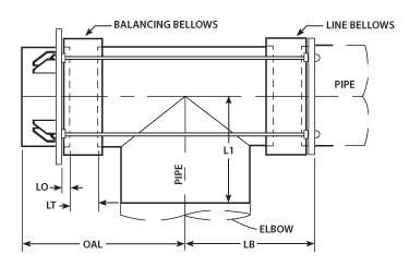
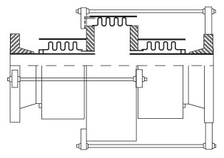
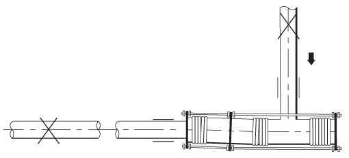
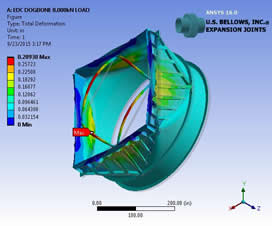
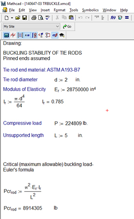
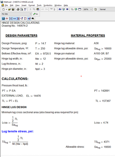
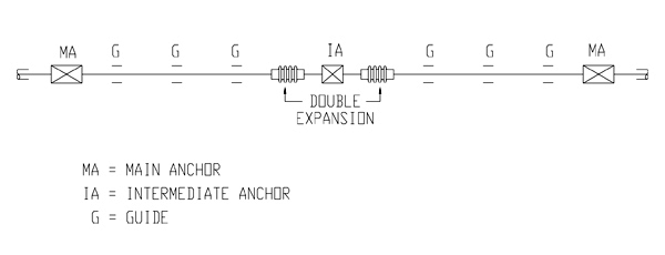
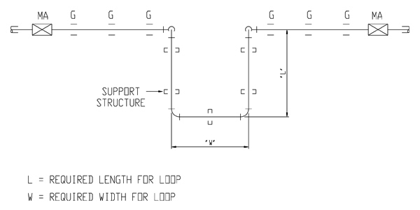
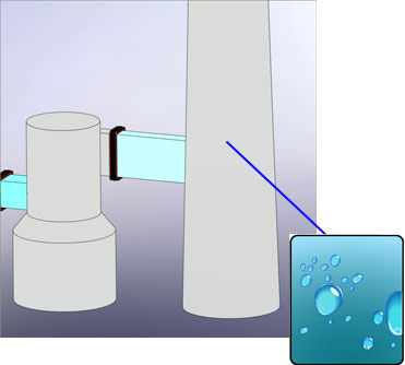
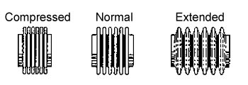
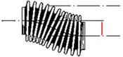
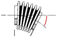
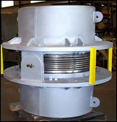
 Expansion joints are often included in industrial piping systems to accommodate movement due to thermal and mechanical changes in the system. When the process requires large changes in temperature, metal components change size. Expansion joints with metal bellows are designed to accommodate certain movements while minimizing the transfer of forces to sensitive components in the system.