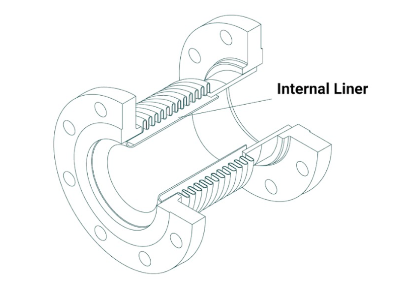
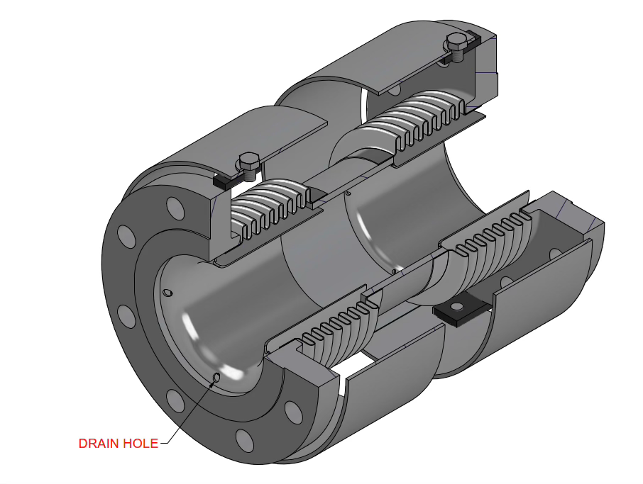
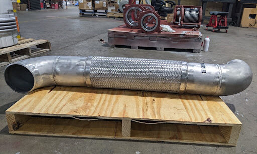
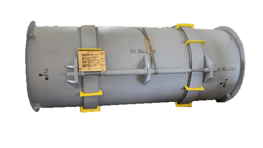
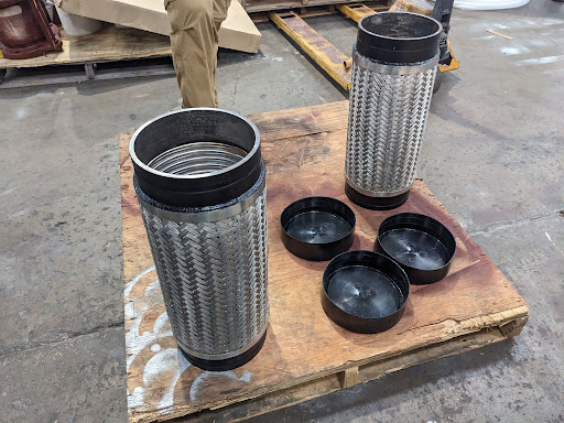
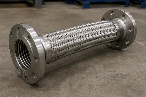
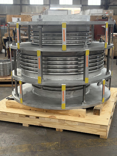
An internal liner gives the flow a smoother path and shields the thin bellows from direct exposure to the process flow. One design question comes with it: what happens to liquid that gets into the space between the liner and the bellows? A drain hole gives that liquid a way out instead of leaving it trapped in the cavity. This article covers where liners with drain holes apply, why drainage matters, and how drain holes compare with purge connections.
Where the Liquid Gets Trapped
The internal liner leaves a gap between its outer surface and the bellows.
Liquid can enter that gap with the process flow.
In a vertical installation, the liner arrangement can form a pocket where condensate or process liquid collects.
Once collected, the liquid has no natural way out.
The design specifications address this directly: “If the stagnant flow medium trapped behind the sleeve is undesirable, drain holes in the sleeve, purge connections, or packing shall be specified.”
💡 Key Insight: A liner protects the bellows from the flow, but it also creates a space behind itself. If liquid can collect there, it needs a planned way out.
Typical Applications
Vertical installations: the liner may create a pocket that retains liquid.
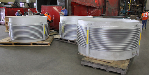
Steam and condensate systems: condensation can form during normal operation, startup, shutdown, or temperature changes. One example of a liner in steam service is a118-inch universal expansion joint built with a 304 stainless steel bellows and liner for a power plant.
Exhaust and flue-gas systems: moisture can condense as the process temperature drops.
Wet-gas service: liquid droplets or condensate can enter the space behind the liner.
Washed or flushed systems: water or cleaning fluids can enter the liner and bellows cavity.
Corrosion, deposit, or freezing-prone services: trapped liquid can harm the bellows.
Why Drainage Matters
Trapped liquid can stay in contact with the bellows for long periods.
Depending on the process and environment, that can contribute to localized corrosion, deposit buildup, freezing concerns, or other deterioration.
If your joint is vertical, sees steam or wet gas, or gets washed down, send us the orientation, media, and operating conditions. We will advise whether a drain hole, purge connection, or neither fits.Schedule time with an engineer to review your application, orrequest a quote for a liner-equipped joint.
Thermal expansion in piping systems is a persistent engineering challenge. Especially in high-temperature process, power applications, seismic zones, and emerging facility types like battery manufacturing plants and data centers. In all of these, pipe runs have to accommodate axial growth and lateral movement without putting excessive stress on anchors, supports, and connected equipment.
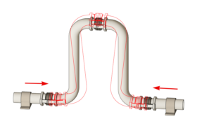
This article looks at three common ways to manage that movement: the conventional pipe loop, the traditional bellows-type expansion joint, and the U-Loop (or V-Loop) expansion joint, a hybrid of the two.
The Pipe Loop: Maximum Reliability & Lowest Maintenance
A pipe loop is built entirely from standard pipe and fittings, bent into a shape that flexes as the pipe heats and grows. Because it uses no specialized components, it carries two real advantages:
The highest reliability of the three options, since there is no bellows to fatigue.
The lowest ongoing maintenance burden, since there is nothing built to a fixed cycle life that needs periodic replacement.
The tradeoff is size and cost:
It needs significant physical space to bend through.
It uses more material and support structure than a compact joint.
It is best suited to primarily axial movement, not combined lateral or angular movement.
US Bellows’ comparison of the two approaches confirms this directly: expansion joints are recommended specifically when there “isn’t enough room to accommodate the large footprint required by pipe loops.”
That same comparison notes pipe loops introduce more pressure drop, from the extra length and elbows in the flow path.
In practice, this rules a pipe loop out for most congested mechanical rooms, retrofits, or overhead routing corridors.
Bellows Expansion Joint
The Traditional Bellows Expansion Joint: Compact but Constrained
Where a pipe loop uses distance to absorb movement, abellows expansion joint uses a flexible metallic bellows instead, absorbing that same movement inside a short, compact section of the line.
That compactness comes with real trade-offs:
A finite fatigue life: The bellows is rated for a specific number of movement cycles, not unlimited service. Misalignment or improper installation during or after commissioning can shorten that life.
Higher Thrust Loads: Anchors will need to be designed for the pressure thrust, as well as follow the guiding requirement.
Ongoing upkeep: It requires periodic inspection and eventual replacement, unlike a pipe loop’s fixed piping.
💡 Key Insight: Compactness saves layout space, but it does not remove the need to design pressure-thrust load paths, guides, and installation tolerances.
The U-Loop (V-Loop) Expansion Joint: A Hybrid Middle Ground
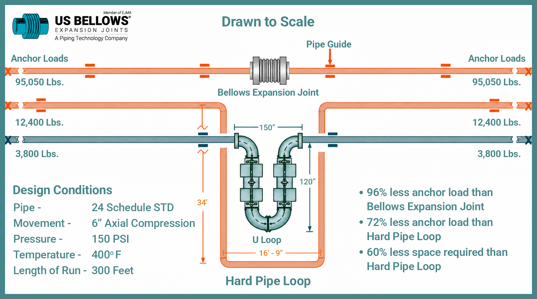
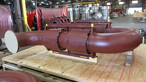
The U-Loop, sometimes built as a V-Loop, combines a shortened pipe loop geometry with bellows elements nested inside it. It is an industry-first design that integrates bellows directly into the loop structure, rather than treating the loop and the joint as separate choices. Together, they significantly reduce the footprint, anchor loads, guiding requirements, and costs.
Two things distinguish it from a standalone bellows expansion joint:
The loop geometry itself absorbs some of the movement, so the bellows inside it can be smaller and the overall assembly more compact than a full-size pipe loop, while needing less specialized anchoring than a bare bellows joint.
Built-in tie rods carry the pressure thrust internally.US Bellows’ U-Loop product page states this “significantly reduces the requirement for numerous anchors,” so the joint absorbs its own pressure load instead of pushing that job onto external anchors, while still keeping the flexibility of a bellows joint.
Super U-Loop for Automotive Plant
This combination is why U-Loops are specified for seismic and high-growth facility applications. APTP article on seismic bracing for data centers describes nested U-Loop configurations handling thermal expansion and seismic movement at the same time, paired with trapeze-hanging supports and guides to keep the piping stable during shaking. US Bellows has also documented a real project on a large-scale battery manufacturing facility: acase study describing:
200+ expansion joints from 4 to 36 inches in diameter.
More than 400 product configurations and over 6,000 total units.
Delivery in about five months, across two production buildings covering chilled water, steam, nitrogen, compressed air, and condensate lines.
A custom nested Super U-Loop configuration, chosen specifically because “large pipe loops were impractical in congested mechanical corridors and overhead routing areas.”
Comparing the Three
Factor
Pipe Loop
Bellows Expansion Joint
U-Loop / V-Loop
Footprint
Largest
Smallest
Moderate
Pressure thrust
Contained by the pipe itself
Must be carried by external main anchors
Absorbed internally by tie rods, reducing anchor needs
Movement handled
Mainly axial
Axial, lateral, or angular depending on design
Thermal movement and seismic displacement together
Cost Considerations
Moderate/High. Depending on the weight, additional support may be needed
Moderate/ High. Although the Bellows is inexpensive, the anchors and guides may bear a significant cost
Moderate Low anchor loading and minimal guiding requirement
Maintenance
Lowest
Periodic inspection and eventual replacement
Periodic inspection, similar to a standalone bellows joint
Choosing the Right Option
There is no single correct answer; the right choice depends on the constraints of the specific system:
A pipe loop is the most reliable option wherever there is enough space, the budget can accommodate it, and there’s only axial movement in consideration
A bellows expansion joint is the right call in tight layouts, provided the anchor and guide system it depends on is properly engineered from the start, not treated as an afterthought.
A U-Loop or V-Loop is worth considering specifically when a project needs the compactness of a bellows joint but cannot support the anchor loads a standalone bellows joint would require, or where thermal and seismic movement both need to be managed in the same run.
The specifics of any one system, pipe size, operating pressure, movement magnitude, and site constraints, still warrant a conversation with an expansion joint manufacturer before a final selection is made.
💡 Engineering Takeaway: Select the movement device and the support system together; the joint cannot be evaluated independently from the piping stress and restraint design.
Space, Seismic, or Simplicity: Which Constraint Is Driving Your Design?
If your layout is fighting you on room, or your site sits in a seismic zone, or you’re just trying to avoid an anchor system the size of the piping run itself, the right answer isn’t the same for every project.Schedule time with an engineer to walk through your specific constraints before committing to a design.
Ready to size a solution for your project?Request a quote, and our engineering team will follow up with pricing and lead time.
AI infrastructure is reshaping how data center piping gets designed. As cooling shifts to higher-density, warm-water systems, higher temperatures, flows, and pressures are driving up thermal movement, nozzle loads, and pressure thrust all at once — making flexible connections a critical design consideration, not an afterthought.
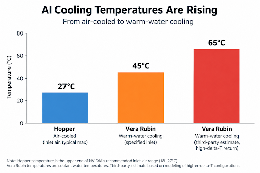
nVidia unveiled this shift at CES in January 2026, announcing that its upcoming Vera Rubin platform would run on 45°C warm water with “no water chillers necessary.” NVIDIA’s reference design describes coolant entering a fully liquid-cooled Vera Rubin rack at up to 45°C (113°F) and exiting at roughly 55°C in typical operation, though third-party modeling has projected return temperatures approaching 65°C in higher-delta-T configurations. Either way, it’s a substantially hotter loop than the chilled-water systems most piping standards were written around.
What changed between Blackwell and Vera Rubin
nVidia’s Blackwell generation (GB200, launched 2024, and GB300, which followed in 2025) already pushed data centers toward direct-to-chip liquid cooling, but ran hybrid — roughly 85% liquid, 15% air. Vera Rubin, entering mass production and shipping in autumn 2026 with cloud partners targeting deployment in the second half of the year, is 100% liquid-cooled: no fans, no air-cooling fallback.
The shift to Vera Rubin compounds several variables at once:
Cooling temperature → flow → pipe size → operating pressure → thermal movement → pressure thrust → nozzle load.
Higher temperature drives more thermal expansion in every pipe run.
Higher flow — reported to roughly double per rack versus GB300 — means more velocity, more turbulence, and more pump-driven vibration.
Larger pipe diameter, needed to carry that flow (row-level distribution has been reported at up to 12 inches, moving around 1,000 gallons per minute), adds thermal mass and force at every fitting.
Higher operating pressure, common in denser, higher-flow secondary loops, generates pressure thrust. Pressure thrust is the unbalanced axial force an expansion joint exerts on its anchors and adjacent equipment when it isn’t restrained by tie rods.
All of it converges as nozzle load at the equipment connection — more connections, more piping, attached to more sensitive IT cooling hardware than ever before.
Individually, each of these is manageable. Converging simultaneously, across hundreds of rack-level cooling units per hall, they’re a new engineering problem.
💡 Hotter water is only part of the story. Higher temperature, flow, pipe size and pressure compound – ultimately showing up as greater loads at equipment connections.
The nozzle load problem… that nobody wants to own
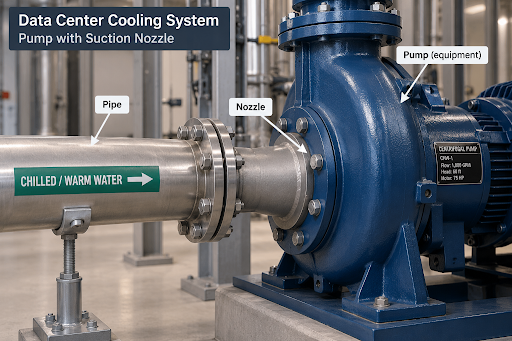
Mechanical equipment can only tolerate limited force and moment at its connections — the “nozzle load.” Exceed it, and you risk cracked welds, misalignment, or seal failure. In high-density liquid cooling, equipment vendors frequently don’t publish allowable nozzle loads at all. New, proprietary hardware on an annual refresh cadence leaves little time for vendors to characterize structural allowables, so engineers must design connections to equipment with effectively unknown tolerances.
💡 When an equipment manufacturer doesn’t publish allowable nozzle loads, the piping designer is left protecting equipment against a tolerance that is effectively unknown.
When the information around how much load a nozzle can take is limited, not readily available, or simply 0 because that is safe and takes no effort for the mechanical equipment vendor, the responsible and possibly move is to minimize the nozzle load. And to account for pressure thrust separately from thermal movement, since an unanchored or unrestrained expansion joint can push just as hard on a nozzle as thermal growth does.
Why flexible connections are the answer
Expansion joints and flex hoses allow the piping to move without putting that stress on the equipment. They absorb thermal expansion, misalignment, and vibration.
That becomes especially important in a Vera Rubin-scale data center, where hundreds of cooling connections may share the same piping system. Without flexibility, movement in the piping can transfer stress to pumps, cooling equipment, and other connections.
Flexible connections let the pipe move while protecting the equipment. Proper anchors and restraints handle the resulting pressure forces.
It’s not just the rack – the whole plant needs to move too
This isn’t only a rack-level issue. The warm-water loop runs through the entire facility plant, and every component has its own nozzles and vibration signature.
Computer room air-handling units (CRAH). Even with direct liquid cooling (DLC), air cooling is still needed to remove heat from the room and control humidity. Water piping connects to cooling coils inside these units.
Coolant Distribution Units (CDU). These are the heart of the liquid-cooling system. They circulate coolant to the server racks and transfer heat between the rack cooling loop and the facility water system. Their pumps and heat exchangers need to be protected from piping movement and vibration.
Air Handling Units (AHUs). Larger air handlers elsewhere in the facility also have water connections that can be affected by pipe movement.
The common problem is simple: the pipes move, but the equipment shouldn’t have to. As cooling systems get hotter and move more water, controlling that movement becomes more important—not just at the server racks, but throughout the cooling system.
Selecting expansion joints when vendor data is undefined
Design to actual movement and pressure. Calculate thermal growth for the specific run length and realistic supply/return swing, and calculate pressure thrust separately — don’t assume legacy chilled-water tables still apply.
Size for flow and velocity, not just diameter. Larger, higher-flow lines generate more turbulence-induced vibration; rate connectors for actual velocity and pressure class.
Treat undefined tolerance as zero tolerance. Without published allowables, design the flexible connection—and its anchoring—to absorb essentially all anticipated movement, vibration, and pressure thrust, rather than splitting the difference with rigid pipe. Good Practice is to allow none of the piping loads to be transferred to the equipment. Keep it at zero load.
Confirm material compatibility. Warm-water DLC loops often run treated water/glycol at elevated temperatures — match elastomer and liner materials to the actual chemistry, temperature, and pressure range.
Plan for serviceability at scale. With hundreds of identical connections, field-replaceable bolted or flanged connectors reduce both installation risk and future downtime.
Document the design basis. Where vendors won’t provide nozzle data, document the calculated assumptions used. It won’t create a number that doesn’t exist, but it creates a defensible engineering record.
As liquid cooling expands, managing pipe movement and vibration becomes more important. Expansion joints and flex hoses help protect expensive cooling equipment by keeping those forces from reaching the equipment connections.
This matters throughout the cooling system — from the server rack to the cooling plant.
Have questions about expansion joint selection for a specific liquid cooling deployment? Our engineering team can help review piping layouts, movement and pressure thrust calculations, and material compatibility for high-density data center projects.
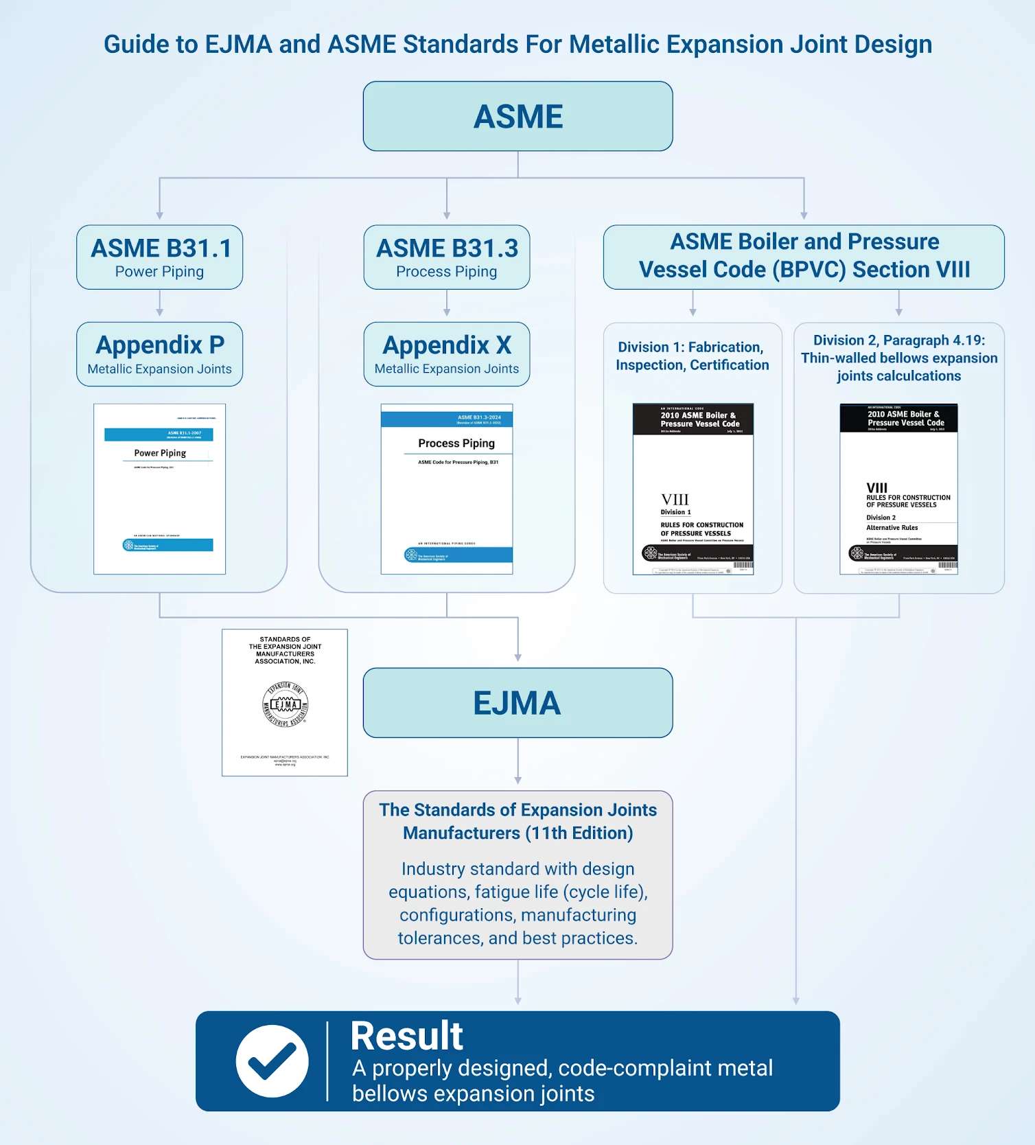
If you work with piping systems, you have probably heard engineers mention EJMA, B31.1, or B31.3. For anyone new to expansion joints or anyone trying to spec, purchase, or inspect one, these codes and standards are not just industry terminology. They are the rulebook that determines whether a joint passes inspections and performs safely over its intended service life. This article breaks down the major codes and standards that apply to expansion joints, what each one covers, and how they work together.
Metal expansion joint
Metal expansion joints occupy an unusual position in piping systems. They are flexible components within otherwise rigid, code-governed piping, and they are expected to accommodate thermal expansion, vibration, and misalignment under pressure. A joint that is undersized, poorly welded, or rated for the wrong cycle life does not just underperform but can also fail under pressure during operation.
This is why expansion joints are subject to overlapping layers of requirements: an industry-specific design standard, an overarching piping or pressure vessel code, and often material and testing standards layered on top. Knowing which applies, and when more than one applies at the same time, is essential to a compliant, safe design.
US Bellows EJMA certification
EJMA: The Industry’s Foundational Design Standard
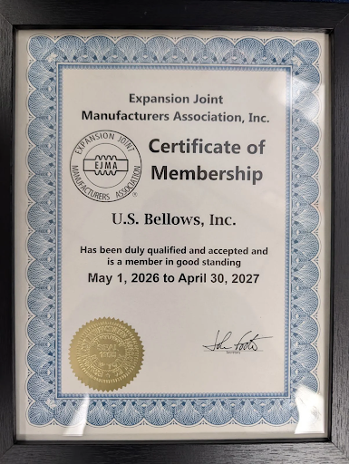
The Expansion Joint Manufacturers Association (EJMA) Standards are the primary technical reference for metal bellows expansion joint design. EJMA is a trade association document, not a government or ASME-issued code. It compiles decades of manufacturer testing data, design equations, and best practices into one reference. US Bellows has beenan EJMA member since 2002, one of 14 member companies worldwide.
Among the topics EJMA’s Standards cover:
Design equations for bellows geometry, pressure capacity, and spring rates
Fatigue life (cycle life) prediction based on empirical test data
Guidance on multi-ply bellows, reinforced designs, and various bellows configurations
Manufacturing tolerances, bellows fabrication, and QC practices
The standard has continued to develop. More recent editions refine equations related to multiple plies, pressure calculations, membrane stresses, temperature effects, and harmonization with current ASME codes. EJMA is not a legally enforceable code. It does not dictate manufacturing, material stress allowables, examination, or quality assurance requirements. Those are set by codes such as ASME B31.3 or a customer’s own specification.
In short, EJMA defines how to design the bellows. It does not define the quality-control requirements needed to prove that it was built correctly. That is where ASME comes in.
ASME B31.3: Process Piping Code
For process piping, the kind found throughout refineries, chemical plants, and industrial facilities, ASME B31.3 is the governing code. B31.3 specifies requirements for materials, design, fabrication, assembly, erection, examination, inspection, and testing of piping systems.
Metallic Bellows expansion joints have a dedicated section: Appendix X. The overall approach adopts the EJMA Standards, with Code Committee modifications that turn EJMA’s industry recommendations into enforceable Code requirements for B31.3 piping. EJMA and ASME B31.3 are not competitors, but they are layered. A joint is generally engineered per EJMA’s design methodology, then verified against the Code requirements in B31.3 Appendix X for the overall assembly.
Fatigue life is where this layering becomes practical for engineers. Bellows vendors often quote two different cycle lives for the same bellows: one calculated per EJMA, and one per ASME B31.3 Appendix X. The B31.3 number is typically lower because EJMA’s fatigue curve is a best-fit average based on test data, while ASME’s curve builds in the design margins expected of a pressure equipment code.
B31.3 also drives requirements beyond the design calculations. Appendix X requires radiographic or dye-penetrant examination of the bellows tube for all metallic bellows, a requirement EJMA does not mandate. B31.3 also imposes its own hydrotesting requirements, testing the joint at the unit’s design temperature, which can require a higher test pressure than expected.
💡 The expansion joint does not “absorb” pressure thrust. Unless the system is designed with an appropriate pressure-restraint arrangement, such as anchors, tie rods, hinges, or gimbals where suitable, the pressure thrust is transferred into connected piping or equipment.
ASME B31.1: Power Piping
Where B31.3 governs process, chemical, and refinery piping, ASME B31.1 (Power Piping) governs piping in power generation facilities: steam lines and similar high-temperature, high-pressure service typical of power plants. Metal expansion joints used in these systems are often specified against B31.1. The applicable design margins and testing requirements can differ, so confirm which code governs a given system before assuming B31.3 rules apply.
ASME Section VIII: Pressure Vessels
Metal expansion joints are not limited to piping. They also appear on pressure vessels and heat exchangers, accommodating differential thermal expansion between shells and tubes. This was historically covered by Section VIII, Division 1, Appendix 26, for bellows expansion joints on vessels operating above 15 psig, which took a different design approach than B31.3’s Appendix X.
As part of ASME’s Section VIII Reshape initiative, the design methodology for thin-walled bellows expansion joints in Appendix 26 was recognized as essentially identical to the method in Division 2, paragraph 4.19. Starting with the 2023 edition, the common design calculations were consolidated into Division 2, with Division 1 referring to that method. Division 1 still governs inspection, testing, and material and certification requirements, but now refers to Division 2 for the underlying calculation methods, as part of ASME’s broader effort to unify calculations across both divisions.
For a bellows on a pressure vessel today, the governing calculations are in Division 2, while Division 1 (Part UEB) covers fabrication, inspection, and certification requirements. Confirm which Code edition a project is built to, since older equipment may still be certified under the legacy Appendix 26 rules.
💡 Establish the code boundary before requesting a quote. B31.3 piping and Section VIII vessel bellows can require different design, inspection, testing, and documentation paths.
Supporting Material and Testing Standards
Beyond the three main piping and vessel codes, several supporting standards apply to metal expansion joint projects:
ASME B16.5 and B16.47: flange dimensional standards, since metal expansion joints are almost always flange-connected into a piping system
ASME B&PV Section V: nondestructive examination methods (radiography, dye-penetrant testing), directly relevant to the bellows tube inspection required under B31.3 Appendix X
ASME B&PV Section IX: welding qualification requirements for the shop welds that join bellows elements, end connections, and reinforcing members
They are the standards a metal bellows is fabricated and inspected against once the EJMA and ASME design work is complete.
💡 A quote comparison is meaningful only when the design basis is comparable. Before comparing price or delivery, confirm that every bidder used the same code edition, movements, cycles, materials, end configuration, pressure test, examination scope, and documentation requirements.
Putting It Together: What This Means for Your Project
For specifying, purchasing, or inspecting a metal expansion joint, a few practical points apply:
Identify the governing piping code first: B31.3, B31.1, or Section VIII. This determines which Appendix and which testing and examination rules apply.
Do not assume EJMA compliance equals Code compliance. EJMA governs the bellows design methodology. The applicable ASME code governs materials, fabrication, examination, and testing of the finished assembly.
Confirm NDE and welding requirements up front. Radiographic or dye-penetrant examination of the bellows tube, along with Section IX-qualified welding, separates a Code-compliant metal joint from one that only looks compliant.
Check for secondary standards or customer specifications relevant to expansion joint fabrication, quality, and testing.
Navigating overlapping codes is specialized work. If it is unclear which standards apply to an application, or a joint needs to be engineered to satisfy multiple codes at once, that is worth discussing with an expansion joint manufacturer early in the design process.
Note: Always consult the current edition of the applicable code and a qualified engineer for project-specific design decisions.
Talk to a Professional
Unsure which codes and standards apply to your expansion joint project?Schedule time with an engineer for a review of your application, or explore our full range ofexpansion joint solutions to see tied, universal, hinged, and gimbal designs.
Ready to move forward?Request a quote, and our engineering team will follow up with pricing and lead time for your application.
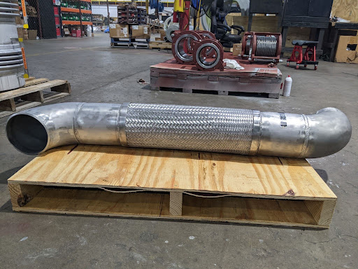
Braided flexible hose and tied expansion joints are both used to restrain pressure thrust while allowing movement in a piping system, and the two are often confused. Selecting the wrong product can result in inadequate movement capacity, unrestrained pressure thrust, or a connection that does not fit the available space envelope. This guide explains what each product is, how each restrains pressure thrust, what movement each is built to handle, and how to decide between them.
What Is a Braided Flexible Hose?
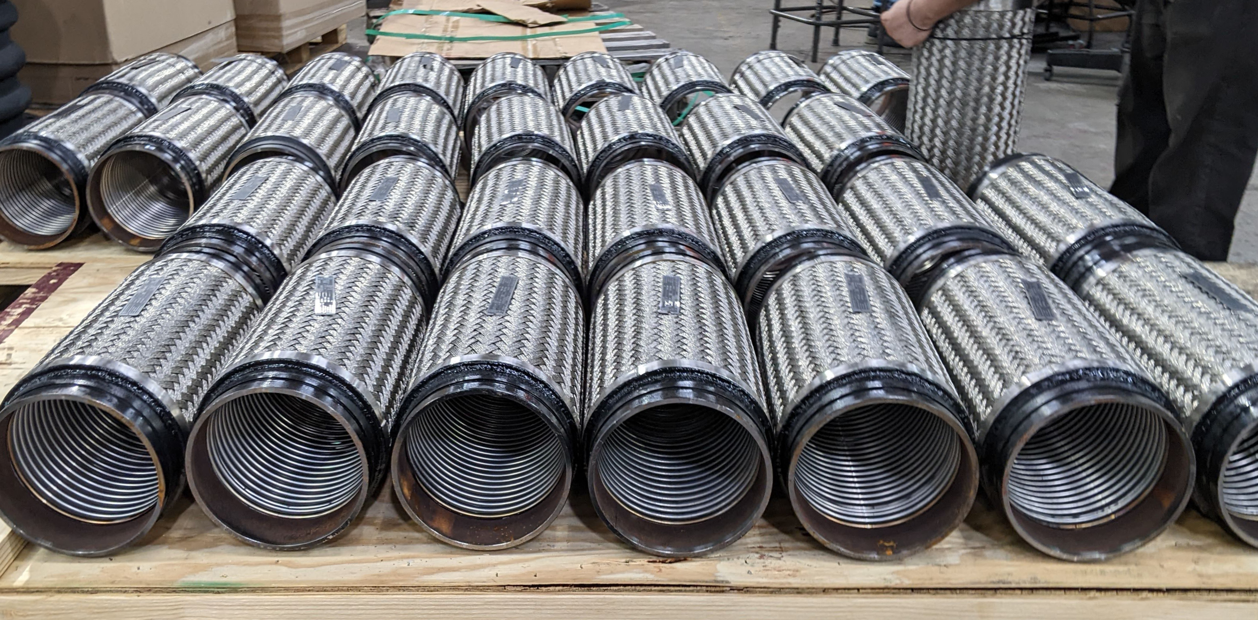
A braided flexible hose consists of a corrugated metallic hose core surrounded by one or more layers of metallic wire braid. The corrugated hose provides flexibility, allowing the assembly to bend or move laterally, while the external braid provides reinforcement and contains the pressure thrust generated by internal pressure.
What Is a Tied Expansion Joint?
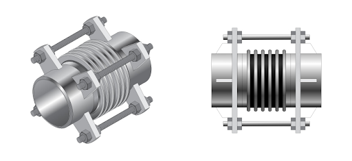
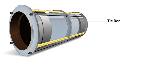
A tied expansion joint is a metal bellows expansion joint fitted with tie rods that run between the assembly’s end flanges through tie-rod lugs. The bellows provide flexibility, allowing the joint to absorb lateral or angular movement, while the tie rods restrain the pressure thrust generated by internal pressure and keep that force from acting on the connected piping or equipment.
Braided flexible hose
How Each Restrains Pressure Thrust
A tied expansion joint and a braided flexible hose can serve similar functions, particularly where lateral movement is required while pressure thrust must be restrained. A tied expansion joint uses tie rods connected to the assembly through tie-rod lugs. The rods restrain pressure thrust while allowing the intended lateral or angular movement. A braided flexible hose achieves the same result differently: the corrugated hose provides flexibility by bending along its length, while the external braid resists pressure thrust and limits axial movement.
When a Tied Expansion Joint Is the Better Choice
A tied expansion joint design, like PTP’stied universal expansion joint, is generally preferred when the application requires:
Larger, controlled lateral movement
A short overall assembly length
Precisely defined movement capability
High axial or lateral structural loads
Large pipe diameters
Specific spring-rate requirements
Engineered movement under thermal expansion
Specialized liners, covers, or flow-control features
When Braided Flexible Hose Is the Better Choice
A braided flexible hose is generally preferred when the application requires:
Installation in a space too tight for tie-rod hardware and its movement envelope
Vibration isolation at rotating or reciprocating equipment such as pumps, compressors, or turbines
Only a relatively small amount of lateral movement
Tolerance for limited installation misalignment between equipment and piping
A simpler assembly that is faster to manufacture, inspect, and replace
A connection that is removed and replaced periodically, such as at equipment that is pulled for service
Selection Guide
Choose Braided Flexible Hose When
Choose a Tied Expansion Joint When
Movement is relatively small
Larger lateral movement is required
Vibration isolation is important
Movement must occur within a short, defined length
A flexible equipment connection is needed
Movement and spring forces must be accurately controlled
Space or installation simplicity is important
The application involves larger piping or significant system loads
Pressure thrust needs to be internally restrained
Engineered accessories such as liners or covers are required
A simple, replaceable assembly is preferred
A specific spring rate is required
Talk to a Piping Specialist
Not sure whether your application calls for a braided flexible hose or a tied expansion joint?Schedule time with an engineer for a review, or explore our full range ofexpansion joint solutions to see tied, universal, hinged, and gimbal designs in detail.
Ready to move forward?Request a quote, and our engineering team will follow up with pricing and lead time for your application.
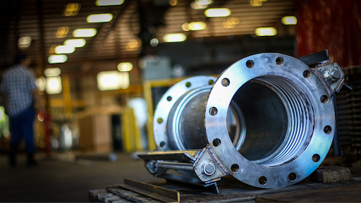
U.S. Bellows custom-engineered and manufactured this impressive 116″ reinforced universal expansion joint for a water supply system in California. Measuring 116″ in diameter and 60″ in overall length, the unit demonstrates U.S. Bellows’ ability to design and fabricate large-diameter expansion joints for demanding infrastructure applications.
The bellows and pipe spool were fabricated from corrosion-resistant AL-6XN stainless steel, while the flanges were manufactured from carbon steel. The bellows were reinforced with AL-6XN round bar in the convolutions to contain the pressure at that volume, as the expansion joint was designed for an operating temperature of 100°F at 220 PSIG and engineered to accommodate 9″ of axial compression.
Before shipment, the completed assembly underwent extensive nondestructive examination and performance testing, including dye penetrant testing, radiographic testing, and hydrostatic testing. These quality-control measures verified the integrity of the welds and confirmed that the expansion joint met the project’s performance requirements.
U.S. Bellows has designed and manufactured engineered expansion joints since the 1960s. The company provides custom metallic, fabric, and rubber expansion joints, along with clamshell bellows, pressure-balanced assemblies, and fabricated ductwork for complex piping and ducting systems. Its engineering capabilities include design in accordance with EJMA equations and applicable ASME standards, as well as in-house finite element analysis for specialized applications.
As a longtime member of the Expansion Joint Manufacturers Association, U.S. Bellows combines specialized engineering, extensive fabrication capabilities, comprehensive testing, and field support to deliver reliable solutions for water infrastructure, refining, chemical processing, power generation, marine, offshore, and pipeline applications. The company also offers emergency engineering, manufacturing, inspection, installation support, and repair services to help customers minimize downtime during critical plant outages and system failures.
In many applications, a tied expansion joint is used to accommodate lateral movement while restraining pressure thrust within the assembly. However, when greater flexibility is needed due to space limitations, vibration, or equipment movement, a braided flexible metal hose can provide a simpler and more practical alternative.
What Is a Braided Flexible Hose?
A braided flexible hose generally consists of a corrugated metallic hose core surrounded by one or more layers of metallic wire braid. The corrugated hose provides flexibility, allowing the assembly to bend or move laterally, while the external braid provides reinforcement and contains the pressure thrust generated by internal pressure.
The braid serves as the primary structural element of the assembly. When the corrugated hose is pressurized, the pressure acting over its effective area generates a thrust, the same force a tied expansion joint must manage. The braid restrains that thrust and limits axial extension of the hose, performing a function similar to the tie rods on a tied metallic expansion joint.
Braided Hose in the facility
When Braided Flexible Hose Can Be Preferred
For the right application, braided hose offers several practical advantages over a tied expansion joint.
Simpler Construction – A braided hose generally consists of just the braid and weld collars that are faster to manufacture, install, inspect, and replace.
Compact Installation – Flexible hose assemblies are well suited to installations where space is genuinely tight. Aerospace piping is a good example: there’s often no room for tie-rod hardware and its required movement envelope, so a properly routed flexible hose delivers the needed movement in a far more compact arrangement.
Vibration Isolation – One of the most common reasons for selecting a braided flexible hose is to isolate equipment vibration. Rotating and reciprocating equipment like pumps, compressors, and turbines transmits vibration into connected piping. A properly designed flexible hose absorbs that movement and reduces how much mechanical vibration reaches the rest of the system.
Small Lateral Movements – When only a relatively small amount of lateral movement is required, a flexible hose is often more practical than a tied expansion joint. The hose accommodates movement through bending distributed over its flexible length. Increasing the available length and choosing the right installation configuration let it accommodate movement without overstressing the corrugations. For larger movements, an engineered expansion joint remains the more controlled, compact solution.
Installation Misalignment – A flexible hose can absorb limited misalignment between equipment and piping, useful when field conditions make perfect alignment difficult. It should not, however, be used to correct severe misalignment or poor installation practice, since permanent misalignment consumes part of the hose’s available flexibility and can shorten service life.
Easier Replacement – Flexible hose assemblies are typically straightforward to remove and replace, which is valuable where the flexible connection is a maintainable component or where equipment is periodically pulled for service.
Braided Hose assemblies in production
Getting the Flexible Length Right
A common mistake in flexible hose design is making the hose too short. Flexible hose accommodates lateral movement through bending, not by stretching axially. If the hose is too short, its bending radius becomes tighter, and the corrugations see higher stress, which can significantly reduce fatigue life. A longer flexible length spreads that movement over a larger section of hose. The same movement-calculation discipline applies to expansion joints; see ourbuyer’s roadmap for calculating movement requirements for the equivalent process on the tied-joint side.
Installation Considerations
Even a correctly designed flexible hose can fail prematurely if installed incorrectly. The hose should be installed so that movement occurs in the intended plane without introducing excessive torsion. Torsion is especially damaging because corrugated hose is designed to flex through bending, not twisting.
Pressure Thrust and Piping Loads
One of the major advantages of both braided hose and tied expansion joints is their ability to contain pressure thrust. In an untied bellows expansion joint, internal pressure creates thrust that must normally be resisted byanchors or other structural components. A tied expansion joint usestie rods to contain that thrust within the assembly; a braided hose’s braid does the same job, restraining axial extension of the corrugated core and transferring pressure-induced forces between the end fittings. Thrust restraint doesn’t mean zero load on connected equipment; however, hose stiffness, bending forces, weight, dynamic loads, and installation geometry all still need to be considered and may still call for properly sizedpipe supports nearby.
Typical Applications
Braided flexible hose assemblies are commonly used for:
Pump suction and discharge connections
Compressor connections
Vibration isolation
General equipment connections
Skid piping
Small thermal movements
Limited lateral movement
Piping misalignment
Connections where equipment must be periodically removed
Space-constrained installations – aerospace piping is a prime example, where a conventional expansion joint would be unnecessarily complex
These assemblies show up across data centers, oil & gas, petrochemical, and other process industries; which product gets specified usually comes down to available space and required movement rather than the industry itself.
Design Standards
Flexible metal hose assemblies are designed and manufactured using recognized industry practices for metallic hoses. Organizations such as NAHAD provide guidance on fabrication, testing, installation, and application. The piping system itself may also fall under an applicable piping code, such as ASME B31.1 or ASME B31.3. This differs from metallic bellows expansion joints, which are commonly designed using EJMA methodology alongside applicable piping or pressure design requirements. One practical consequence: braided hose doesn’t have an equivalent standard for estimating service life the way EJMA-designed tie rods do, so inspection and replacement intervals are typically set by application experience rather than a published life calculation.
Frequently Asked Questions
Does a braided flexible hose allow the same movement as a Tied Expansion joint? This is a common misconception worth clearing up: neither a braided flexible hose nor a tied expansion joint accommodates axial (straight-line stretching) movement; both are restrained against that by design. What they allow is lateral and angular movement: the hose through bending along its flexible length, the tied joint through controlled bellows deflection.
How long does a braided flexible hose last compared to a tied expansion joint? There’s no industry standard or code for calculating a braided hose’s expected life cycle the way EJMA methodology allows for tied, engineered expansion joints. In practice, tie rods and bellows designed to EJMA guidelines are generally expected to outlast a braided hose in continuous service, so periodic inspection and a planned replacement interval are recommended for hose assemblies.
Which industries use braided flexible hose most? It shows up across data centers, oil & gas, petrochemical, and general process industries, plus space-constrained fields like aerospace where there simply isn’t room for tie-rod hardware. The deciding factor is usually available space and required movement, not the industry itself.
Talk to a PTP Piping Specialist
Not sure whether your application calls for a braided flexible hose or a tied expansion joint?Schedule time with an engineer for a review, or explore our full range ofexpansion joint solutions to see tied, universal, hinged, and gimbal designs in detail.
Ready to move forward?Request a quote, and our engineering team will follow up with pricing and lead time for your application.
Tie-rods with hex nuts and lugs on a metallic expansion joint
In a restrained expansion joint assembly, the hex nuts on a tied expansion joint are intentionally positioned with a measured gap between the nut and the lug. Customers frequently ask whether this clearance is necessary. The answer is yes – it is a critical design feature that allows the expansion joint to function as intended while protecting the bellows from excessive loads.
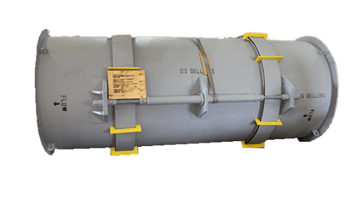
While “control rod” and “tie-rod” are sometimes used interchangeably in the expansion joint industry, they serve different functions. Tie-rods are meant to continuously restrain full pressure thrust and permit only lateral movement during normal operation (i.e, there’s no gap in between the rods and nuts). Control rods are meant to prevent over-extension or compression (i.e, there’s a gap in the rods and nuts), and are designed to contain the full pressure thrust in case of an anchor failure.
This article explains the purpose of the clearance between the nuts and the lugs and how it is determined during design. We will also look at consequences for the piping system when it is altered in the field.
Tie rod assembly on a metallic expansion joint
What Is the Nut and Lug Clearance?
An expansion joint is designed to absorb movement in a piping system. As the line heats up and cools down, the pipe expands and contracts, and the bellows compress and extend to absorb that movement, preventing it from transferring to the surrounding piping and equipment.
Thetie rod assembly is the hardware that controls this movement (normally lateral movement). It consists of three components:
Tie rods: Rods that span the joint from one end to the other
Ear plates (lugs): plates welded to each end of the joint that the rods pass through
Hex nuts: positioned on the rods based on the movement at the lugs
Tie Rod, Limit Rod, or Control Rod?
In the field, the terms tie rod, limit rod, and control rod are often used interchangeably, and they can refer to hardware that looks nearly identical: a threaded rod passing through lugs, held by hex nuts. They are, however, technically different components, and the distinction matters when specifying an expansion joint.
Atie rod continuously restrains the full pressure thrust of the system during normal operation and permits only lateral deflection. Alimit rod allows the joint to move within its designed range, limiting axial expansion or compression, and restrains the pressure thrust only in the event of an anchor failure. A control rod is used on universal expansion joints to limit and control the movement of the assembly. The correct term depends on the function the rod performs, and each is custom-designed based on the pressure and load forces of the specific application.
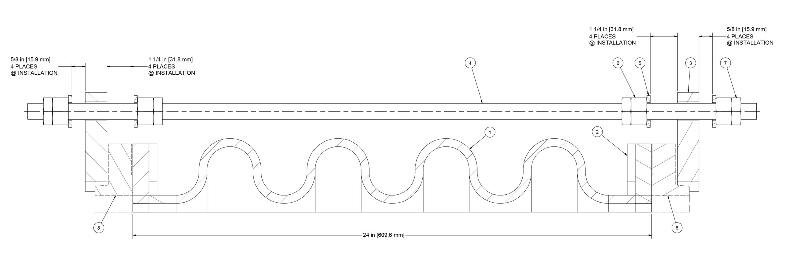
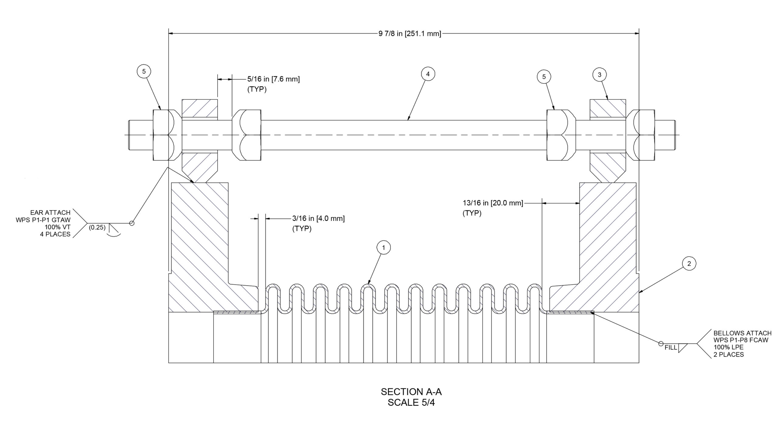
The clearance is the deliberate gap left between the hex nut and the lug. That gap allows the bellows to move and compress without damaging the equipment. Within it, the joint moves freely as the pipe expands and contracts, and the gap defines the limit of that movement.
Single metallic expansion joint
Universal expansion joint with tie rods
–>
How Is the Gap Calculated?
The clearance is not a standard dimension. It is unique to each expansion joint design and is determined by the engineering team based on the movement requirements of the application.
Designed for 2.25″ Compression and 1.25″ expansion for Single EJ
Single expansion joints – For a single expansion joint, the engineering team divides the total travel requirement in half and sets that value as the clearance on each side of the lug. For example, if a joint is designed for 2 inches of total axial travel, that travel is split across the two sides: a 1-inch gap is set between the nut and the lug on one side, and a 1-inch gap on the other. The joint is free to move within these clearances, and the nuts stop it from traveling beyond them.
Designed for 5/8″ Compression EJ
Universal expansion joints – A universal expansion joint consists of two bellows separated by a center pipe section, or spool, and is designed to absorb large amounts of lateral deflection. Because the movement is distributed across two bellows, the clearance cannot be set by simply dividing the travel in half. The engineering team determines the clearance dimensions specifically for each design.
Improper installation in either direction puts the system at risk.
When the Gap Is Closed (Nuts Tightened Against the Lugs)
Tightening the nuts against the lugs prevents the expansion joint from moving axially. The joint can no longer absorb the expansion and contraction of the pipe, and the thermal stress is transferred to an anchor or equipment in the piping system, which may cause a failure on either of those structures.
When the Clearance Exceeds the Design Specification
Excessive clearance allows the expansion joint to move beyond its designed travel. If the joint is not designed to handle that level of movement, this can lead to premature failure of the unit.
Set in the Shop, Guided by the Drawings
Every assembly is fabricated and assembled at our facility before shipping. Customers generally do not need to perform any field welding on these assemblies. Where field work is required, we provide the drawings needed to guide correct installation.
Takeaway
The clearance gap between the nuts and the lugs is part of the design. It allows the expansion joint to move as intended and defines the limit of that movement. The nut positions on a new assembly are set to the design dimensions and should not be adjusted during installation or maintenance.
When one of the world’s leading uranium producers faced an urgent need for a critical piping component at their Canadian mining operations, US Bellows delivered. Engineered and fabricated on an emergency rush basis, this 36” NPS Inline Pressure Balanced Expansion Joint is a testament to our team’s ability to respond fast without compromising quality.
Completed expansion joint ready for shipment
The Application
The unit was designed to handle dry sulfur gas (SO₂/SO₃) — one of the most aggressively corrosive media encountered in industrial processing. The Pressure balanced expansion joint is placed between the converter and the boiler. Operating within a uranium conversion facility, the expansion joint serves to absorb thermal growth in the piping system while maintaining zero net pressure thrust loads on the connected converter — a critical equipment in the plant where chemical reaction of the contact process takes place.
The Design
Rated for 1,196°F at +/-14.5 PSIG (Full Vacuum) and 2.75” axial movement, the 36” unit features a pressure balanced configuration: three bellows of different diameters — two line and one balancing — working in tandem to cancel out pressure-induced forces so that no axial load is transmitted to the connected nozzles. The entire assembly, including bellows, liner, and structural hardware, was fabricated from 304H stainless steel, the high-carbon austenitic grade selected for its superior creep resistance at extreme temperatures. A full-bore internal liner protects the bellows from direct gas impingement and flow-induced vibration.
The expansion joint long seams of both the pipes, as well as the bellows were all 100% Radiography examined. Other pressure retaining areas were dye-penetrant examined. The complete expansion joint examined was leak-tested after completion.
Rapid Response, No Compromises
What makes this project stand out is the timeline. The request came in as an Emergency on Sunday, US Bellows responded within minutes of the request. From receipt of order to ship-ready unit, US Bellows compressed what is typically a multi-week fabrication cycle into an emergency turnaround completing fabrication on Thursday, only 4 days from the receipt of call on Sunday— mobilizing engineering, materials, and shop resources in parallel. For a mining and milling operation, every day of downtime carries significant operational impact. Our ability to execute under that kind of pressure, while meeting all design and quality requirements, reflects the depth of experience and flexibility that sets US Bellows apart.
US Bellows Capabilities
This project highlights several core strengths that we bring to every job:
Emergency & rush fabrication — rapid response without sacrificing engineering and Quality
Corrosion-resistant materials expertise — selection and fabrication in stainless and high-alloy grades
High-temperature applications — engineered for extreme thermal and process conditions
Custom engineering — every unit designed to the specific demands of the application
US Bellows specializes in the design and manufacture of metal expansion joints for the most demanding industrial applications. Contact us to discuss your project.
U.S. Bellows Designed and fabricated single expansion joints for a chemical processing facility in Canada. Designed for 4-inch piping, each expansion joint accommodates 1 inch of axial movement with a spring rate of 425 lb./in. The units come with covers to protect the bellows during installation and operation. The units also have control rods to prevent any excess movement from the expansion joint and are designed to contain the pressure thrust in case of an anchor failure. The expansion joints are rated for a design pressure of 150 PSIG at 300°F, ensuring reliable performance under demanding operating conditions.
To verify quality and performance, each expansion joint underwent 100% dye penetrant examination and a hydrostatic pressure test prior to shipment, ensuring compliance with the project’s stringent quality requirements and providing the customer with a dependable, high-quality solution.