general-questions-faq
Yes, we would recommend that the expansion joint is filled with Kao, but it would require a special design or over-sized bellows.
We obtain the MTR’s and additionally we perform positive material identification tests in house and if a customer requires additional the additional chemical and physical properties, we can obtain that as well.
A double offset expansion joint can be used to absorb large amounts of lateral motion with a minimum amount of deflection forces
Bellows have corrugations (convolutions) in order to be able to absorb the thermal movement of the piping.
We punch form our bellows. This is an industry accepted forming method.
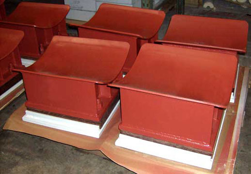
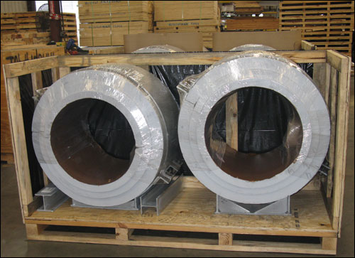
There are a variety of places for the insulation pillow to be placed within the expansion joint. It can be inside the unit or we can fabricate the expansion joint over sized and we can fill the extra space with the insulation pillow for example to reduce the skin temperature of the fabric.
The location of expansion joints in a piping system depends on the design conditions and the piping system configuration. All cases must be evaluated individually.
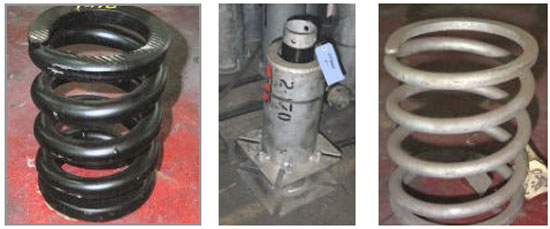
Use a center spool support to support the weight of the spool between the bellows and to stabilize the center spool during operation.
Kaowool is used. It is a ceramic thermal blanket.
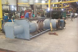
Pressure balance type. The major advantage of a pressure balanced joint is its ability to absorb axial movement without imposing additional pressure thrust into the piping system.
Fatigue life of any unit has to be calculated. The number of cycles varies according to the design conditions of the expansion joints.
If you use a two-ply bellows, each ply can be designed for the full temperature and pressure conditions so that if the inside ply were to fail, you would still have the outside ply to carry the design pressure and temperatures.
This expansion joint is also known as an Omega bellows pipe expansion joint for it resembles the Greek letter Omega.
Design condition of bellow prescribes physical dimension and shape of convolution. It also depends on a combination of size, temperature and pressure. The image of the rounded corner below is an example of an U-shaped design.
1″ nom diameter.
There is not a particular time period of service life, but it depends on the environmental condition of the expansion joints. Maintenance is not required on expansion joints.
Hinged expansion joints are used in conjunction with piping loops in order to absorb large amounts of thermal expansion.
There is not an acceptance criterion for bolt to fabric connection.
An expansion joint is typically installed in compressor inlet or outlet piping to reduce the forces and moments on the compressor nozzles.
Flow direction of an expansion joint refers to the direction by which the material within the pipe is moving.
The bellows outside the elbow is called the balancing bellows. This bellows compensates for the movements. The elbow acts as an intermediate anchor and the tie rods absorb all of the pressured thrust forces.
The function of tie rods on an expansion joint is to continuously restrain the full pressure thrust during normal operation while permitting only lateral deflection. Limit rods are used to limit axial expansion or compression. Limit rods are designed to absorb the pressure thrust of the expansion joint in case of anchor failure.
A bellows is the flexible element of an expansion joint consisting of one or more convolutions and the end tangents, if any.
Lateral deflection is movement perpendicular to the axial plane of the expansion joint. It is a shear motion on the bellows.
Free length is the neutral length of the expansion joint bellows. This is the length of the bellows that has neither been compressed nor extended.
The flow rate is the amount of liquid passing through a particular area over a period of time. It is generally measured in gallons per a minute or cubic feet per meter.
O.A.L refers to the overall length of the expansion joint.
Bellows I.D. refers to the inside diameter of the bellows.
A swing expansion joint is another term used for a hinge type expansion joint.
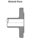
Engineers need to select the right connection hardware to ensure a secure seal when assembling piping systems. An RFSO flange is a common choice for these applications.
The abbreviation RFSO stands for “Raised Face Slip-On.” This specific “Slip-On” design allows the component to slide directly over the end of the pipe before being welded in place. The raised face part of the flange concentrates the pressure load onto a smaller gasket area, improving its sealing capabilities when compared to a flat-face flange.
There are several different ratings or “classes” for these flanges; the higher the class, the higher the pressure rating, with class #150 being the lowest and most commonly used rating. These components are generally preferred for low-pressure applications where easy alignment is needed during installation.
RFSO Flanges are a type of pipe flange on the edges of expansion joints in which the bolting circle face is slightly elevated. Moreover, as a slip-on flange, it can slide over the pipe to provide a better seal and protect against leakage. This is best used in low-to-moderate pressure applications, and is preferred in situations where welding access is easier and lower-cost fabrication is desired.
When an expansion joint experiences bending about its center, which is on the centerline and halfway between the ends of the bellows, this deflection is referred to as angular. It can occur in any plane that passes through the centerline, but the plane should be clearly indicated if the expansion joint is more complicated than the simplest type, i.e., only a bellows with flanges or pipe ends. As in lateral movements, piping analyses may reveal angular deflections occurring in more than one plane. With angular deflection the basis for the proper selection is the maximum of the various deflections, and not the vector sum as in the lateral case. Multiple angular deflections in multiple planes produce a single angular deflection in a single resultant plane. As in lateral deflection, this plane must be understood if structural components are to be used.
An FCC unit is a fluid catalytic cracking unit, which is a type of process that is used in refining crude oil into gasoline. The expansion joints used for the service are called stand pipe expansion joints.
An expansion joint is an assembly used in a pipe line to allow it to expand and contract as climate conditions move from hot to cold and helps to ensure that the system remains functional.
This is an expansion joint specification meaning the expansion joint is rated for 300 pounds per square inch of pressure.
This may result in the belt fluttering. The fabric will fatigue over time resulting in tears. Using stiffer fabric material, installing a liner and increasing the standoff are steps to take avoid flutter.
Cold preset of 2.5″ is performed in the shop on one side of the center line so that in operation the expansion joint will return to the neutral position.
Expansion is caused by heat being applied to a piping system.
On slip type pipe expansion joints special features such as wipers can be included to prevent clogging of the space provided for slip movement.
The limiting factors correspond to the limiting factors of the bellows design in accordance with the specifications of each expansion joint.
The three basic movements within an expansion joint are axial, lateral, or angular rotation. All three of these movements do not generally occur at the same time.
The anchors are located at the lower floor and upper floor of chilled water risers and guides should be located on alternating floors. The expansion joints should then be located near the main anchors.
An intermediate anchor is a stop in the piping system that divides the movement between expansion joints.
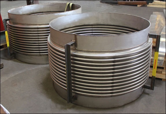
When specifying expansion joints for industrial piping, or any application, understanding the anatomy of the flexible element is essential. A common question from engineers is what convolutions are and how they function. Convolutions are the specific folds or corrugations formed into the thin metal cylinder of the bellows.
These engineered ridges give the expansion joint its flexibility, allowing it to compress, extend, or deflect angularly in response to thermal expansion and mechanical movement.
By incorporating precisely designed convolutions, the bellows can safely contain the pressure of the system while maintaining a tight seal and absorbing the thermal movement of the line, ensuring the long-term reliability of the piping infrastructure.
FAQs
Q: How do convolutions manage thermal expansion in pipelines?
A: As the pipe expands or contracts due to temperature changes, the convolutions flex, compressing or extending, to absorb the movement without transferring destructive stress to the surrounding structural steel or equipment.
Q: Does the shape or depth of the convolutions affect system performance?
A: Yes, the precise profile, height, thickness, and pitch of the convolutions directly dictate the expansion joint’s flexibility, maximum pressure rating, and overall cycle life.
Q: Why are engineers often asking what convolutions are when replacing older piping components?
A: Understanding the exact physical limits and movement capabilities of an existing expansion joint and its convolutions helps engineers correctly size and select the appropriate replacement bellows, preventing premature mechanical fatigue and system failure.
We generally use universal primer for expansion joints, unless the customer specifies a specific paint.
Yes, the limit rod will prevent damage of expansion joint in case of anchor failure in the line. Also, the rod will prevent damage to the expansion joint by distributing the movements evenly between the bellows
US Bellows, Inc. designs bellows for condition requirements.
The branch of a balanced Tee is in the flow path.
It depends upon the diameter of the expansion joints. Generally for the smaller expansion joints, seamless is available.
It depends upon the pipeline design. For example, if there is a long run of pipe on both sides, then we need guides on both sides. If the expansion joint is located close to an anchor, then guides are only required on the long side.
You should never punch a hole into an expansion joint.
Yes, this expansion joint is obviously more expensive than the similar types, however they may result in a lower overall system cost when the elimination of main anchoring is considered.
Yes, it is safe to use 304 Stainless Steel, but high alloy materials such as Inconel® and Monel® are better options for a salt water atmosphere.
Expansion joints should be pre-compressed for low-temperature/cryogenic applications because when the pipe gets cold it will contract.
We have standard lengths that are listed in our catalog, however, we can make our expansion joints longer or shorter than what our catalog states. We also can furnish piping assemblies with pipe and fitting as may be required.
Buckling typically occurs while the pipe in compression mode and is not normally related to the tension mode of the pipe.
The expansion joint cycle is a design condition – stated by the customer or a number we provide according to the design of the expansion joint which refers to the expansion joint moving from the neutral position to compression and back to neutral.
We recommend the use of furnace bags to seal high temperature tubes that penetrate the furnace floor.
In order to remove an expansion joint from a pipeline you must first shut off the fluid or gas flowing through the piping system. Then you must install braces across the bellows so that the expansion joint does not move. The expansion joint can then be removed by unbolting the flanges or cutting the expansion joint out of the pipeline.
As a minimum the following information should be provided when ordering an expansion joint:
-
Size of the line.
-
Design pressure.
-
Design temperature.
-
Design movements and required cycle life.
-
Overall length requirement, if any.
-
Type of end connections.
-
Bellows material.
-
Pipe material.
-
Flange specification and material.
-
Type of expansion joint.
-
Accessories.
The number of convolutions is based upon EJMA design formulas for bellows.
Connecting duct pipe with expansion joints can be accomplished by using angle iron flanges, weld bands or butt welding.
A copper tube can be attached by brazing or soldering the tube to the bellows.
The anchoring and guiding of any expansion joint system would be per EJMA standards. Elevated piping systems will usually use some type of tied expansion joint to eliminate main anchors.
Tie rods on expansion joints are factory set in the manufacture process and should not be adjusted in the field.
The flow end bellows will compress and the balancing bellows will extend because they are connected by the rods.
An external cover can be provided as an accessory to expansion joints so that insulation can then be placed over the expansion joint unit.
The expansion joint can be replaced by an expansion joint of a similar design in the cold condition (when the plant is shut down). Shipping brackets should be placed on the expansion joint before un-flanging or cutting the expansion joint from the system.
Design life is fatigue life which is also the cycle life. They are all the same thing.
Expansion joints are not installed inside furnaces due to the extremely high temperatures of the environment and the piping system. Expansion joints will typically be found in the piping coming in and out of the furnace.
A bellows functions by compressing or extending according to the axial motion that is required in the piping system.
The expansion joint should be located as close as possible to the main anchor. The first guide should be 4 pipe diameters from the expansion joint. The second guide should be 14 pipe diameters from the first guide.
They are installed before the fabric belt installation. Telescoping liners are welded on each side of the expansion joint, either on inner diameter base of flange or inner diameter of pipe. Liner seal is held by clips that are also welded on the inner diameter of the liners.
Seals are retained with clips and welded to the inside diameter of the liner.
Holes should never be punch on or in expansion joints.
The joint frame takes the place of the stiffener flange.
Yes we do provide lifting lugs. Whether or not we provide them depends upon the size and weight of the unit.
Not normally, it all depends on the service condition or application of the expansion joint.
No, expansion joints are good for thermal or operating movements only. They should not be used for any misalignments or to close any gap while installing.
No, intermediate anchors are typically used to divide the pipeline into sections and therefore multiple expansion joints can be used to divide up the thermal expansion.
Slip joints transfer pressure thrust & spring forces into system unlike pressure balanced units.
We do not include the vibration calculations in the normal design calculations, however, if you provide the natural frequency of the vibration, we can consider it.
There will be reduction of the pressure capacity of the bellows.
Compared to stainless steel, carbon steel has modulus of elasticity at a higher temperature
We can send technicians to the field for certain repairs, however, it depends on the extent of the repair.
Yes, the gimbal hardware of a gimbal expansion joint can be designed to support the weight of adjacent piping.
Yes we are able to perform finite element analysis for bellows design. Normal bellows design is based on EJMA equations.
We do not make bellows out of titanium but every material has their fatigue cycle. Titanium has higher stress allow-ables at temperatures but it does not mean they have infinite cycle life.
Yes there are and US Bellows, Inc. can design and manufacture these.
Some hinge types can be provided with hinge pin holes which are slotted to permit limited axial travel. These slotted hinge types will not resist pressure thrust forces, and anchoring must be provided.
Liquid Natural Gas – It is light hydrocarbon gasses that are compressed into a liquid state for cheaper and more efficient transportation.
Thermal expansion caused by temperatures dropping to negative temperatures — commonly called contraction.
We typically use four methods of protecting carbon steel pipe supports components from corrosion; painting, zinc coatings, hot dip galvanizing, and combinations of these. For an in-depth analysis of each method, click here.
When calculating your pipe thickness, you want to take a few parameters into consideration:
Hydro-test pressure and holding times vary for different design codes. For example, the ASME SEC VIII Div.1 general hydro-test pressure will be1.3 x design pressure (minor factors may vary for this equation as well) and for piping design codes, the hydro-test pressure will be ASME B31.4,B31.8 1.5 xdesign pressure.
Some examples of solids that could be transported through a pipe are plastic pellets, powders, grain, coke from a coking unit, grain, etc

Powder
Anchors will restrict movement in all directions and will also restrict the rotation of the pipe as well. In the stress analysis, we may see loads in all three directions which will tell us how “strong” the anchor device has to be.
From the maximum sag we calculate the natural frequency andthat maximum value which should not exceed 4 cycles per second.
Lateral Deflection
Sag is the deflection of pipe between the supported ends.
Thermal bowing is the bending of pipe caused by thermal expansion.

Our spring hangers, constants, and variables are already in Caesar II – Rigid supports can be modeled as stops or restraints in the direction required.
A load cell is only the measuring device forcalibration and it is used to test all our spring cans and constants.
An isolation pad material isbelting material designed to absorb shock.

Isolation Pad on a Hold-Down Pipe Clamp
Yes, thehigher the density the higher the thermal conductivity.
Yes, the fluid will be considered as a varying load. Additionally, when you design for the load, you include the weight of the pipe and the fluid flowing through it.
STAAD analysis is a program we use for structural analysis, specifically to design auxiliary steel which is basically, the length between the structural steel designed by our engineering department and the extra supplementary steel required to support the additional supports which are beingutilized to support the piping system.
The failure criteria is a permanent deformation greater than 3% is considered a failure for that particular batch.
The answer to this is both. We check the individual pieces before we put the support together, then we check the final assembly before it ships.

Inspecting Permali Insulation Prior to Assembling Pipe Shoes
Yes, the fluid will be considered as a varying load. Additionally, when you design for the load, you include the weight of the pipe and the fluid flowing through it.
Per MSS the maximum deviation from the published spring rate for any spring would be +/-10%. Consequently any decay greater than10% would be unacceptable.
A 3-coat paint system consists of a primary coat, an intermediate coat, and a top coat of a color or finish typically specified by the end user.

Steel Structural Supports with a 3-Coat Paint System
Axial pipe restraint means that the support will incorporate some means of positively restricting the movement of the supported pipe along its longitudinal access in line with the pipe.
To double nut a pipe hanger, add an auxiliary nut at each threaded junction to lock against the support components to prevent rotation during operation.
You mayeither send an e-mail to info@pipingtech.comwith all of the details of your quote request, or you may fill out the convenientform at the link below:
In general, the procedure of painting carbon steel material acts asprotective coating to inhibit rust and/or any other chemical reactions in thesurrounding atmosphere.

Painted Constant Spring Supports
Axial pipe movement would be defined as the movement along the centerline axis of the pipe system.
Neoprene coating is generally applied to pipe support components thatrequire flexibility such as spring coils whereas the hot dipped galvanizingcoating would be applied to rigid pipe support components.
Spring Coil with Neoprene Coating
We providea variety of insulation materials including Micarta, G10, Permali, CalciumSilicate, Firetemp, FRP and Polyurethane. These materials are used for eitherhigh temperature or low temperature pipe supports. They serve a variety ofapplications, loads and temperatures.

Permali Lining for Cold Shoes
Galvanized steel is a metal alloy of iron and carbon that has been coated with a type of sealant to protect thematerial against corrosion. It has two advantages over a zinc coating. Duringgalvanizing, the molten zinc reacts with the carbon steel to form layers ofzinc/iron alloys. The alloy layers between have increased hardness to providemechanical (barrier) protection and because of their zinc content they are alsoanodic relative to carbon steel. The hardness of these alloy layers providesmuch more protection from scratches than paint can provide.

Galvanized Steel Clevis Hanger
Galvanized coating is a type of sealant to protect a pipe support against corrosion. It has two advantages over a zinc coating. During galvanizing, the molten zinc reacts with the carbon steel to form layers of zinc/iron alloys. The alloy layers between have increased hardness to provide mechanical (barrier) protection and because of their zinc content they are also anodic relative to carbon steel. The hardness of these alloy layers provides much more protection from scratches than paint can provide. This is important for most pipe supports applications.

Constant Spring Assemblies with Galvanized Coating
The burst test is primarily conducted on bellows. Normally, hydraulic pressure is slowly increased until failure occurs. Based on the burst test results, a safety factor is applied. This establishes the ultimate pressure rating.

Burst Testing
The objective of the burst test is to determine the ultimate pressure resistance. This test is primarily conducted on bellows. Normally, hydraulic pressure is slowly increased until failure occurs. Based on the burst test results, a safety factor is applied. This establishes the ultimate pressure rating.
Burst Testing
EDI stands for Electronic Data Interchange. PT&P regularly conducts electronic data interchange with customers. We dedicate an in-house team of software developers and integrators to setup intra-company electronic processes that increase data accuracy and reduce cycle time.
At Piping Technology & Products, the density of the polyurethane that we offer 10 lb./cubic ft., 15 lb./cubic ft. and 20 lb./cubic ft. and 32 lb./cubic ft.
Permali® is a high density insulating material comprised of layers of beech wood. The total insulation thickness is obtained by bonding the individual layers. This material is primarily used in cold temperature applications ranging from ambient conditions down to -300 degrees F.