|
||||||


Read More
![]()
US Bellows is a Standards Subscriber | Exp: Dec 31, 2026 | See ejma.org to check verification process
Celebrating over 20 years of EJMA membership
|
||||||
Read More
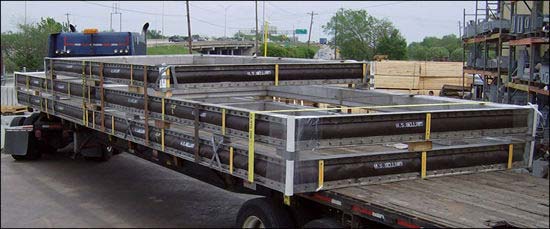
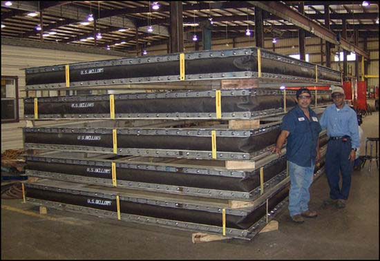
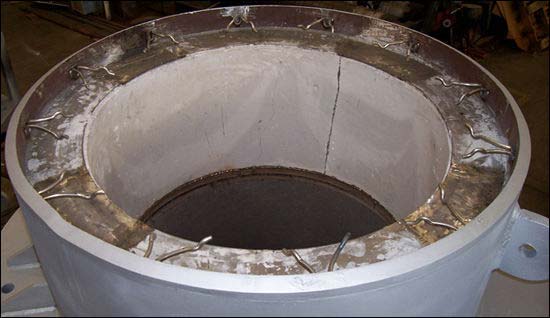
The fabric expansion joints shown above are fabricated with a three layer fabric belt. The three layers consist of an inner layer of silica cloth, a middle layer of mineral wool and an outer layer of PTFE/coated fiber glass. The frame includes an insulation blanket of mineral wool and stainless steel wire mesh. The frame and liner are fabricated from 3/8″ thick 304 stainless steel and each expansion joint’s frame and liner welds were dye-penetrant tested before shipping.
 |
Design:
Design Movements:
|
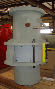
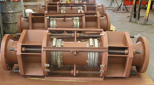
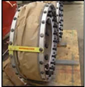
U.S. Bellows, Inc. designed and fabricated 36″ pressure balanced elbow expansion joints that weigh approximately 4,300 lb. each. The pressure-balanced design does not exert pressure thrust on the equipment in the piping system. The expansion joints are designed with Inconel® 625 grade LCF bellows and include a liner provided with drain holes to prevent the accumulation of corrosive condensation. The design movements are 1/2″ axial compression and 3/4″ lateral movement. The bellows were 100% x-rayed before forming and dye-penetrant examined after forming.
Read More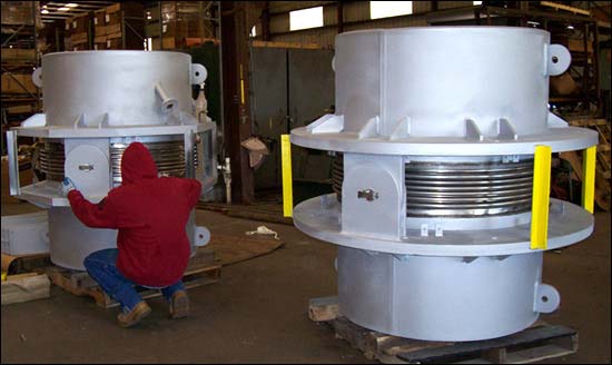
 |
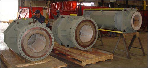
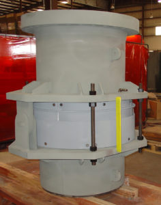
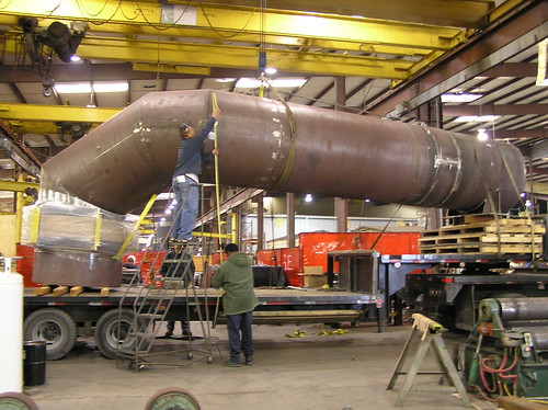
U.S. Bellows, Inc. designed and fabricated two 44″ hinged expansion joints with 5″ thick refractory lining. These expansion joints are part of FCC stand-pipes in a synfuels plant. Each expansion joint is fabricated of two-ply Inconel® bellows and 3/4″ wall pipe. The joints consist of 2″ thick attachment rings. After fabrication, the expansion joints were pneumatically tested and inter-plies tested. The bellows and pipes were 100% x-rayed and PMI tested. |
Thermal and structural Finite Element Analysis (FEA) was performed on the expansion joints to ensure the product is structurally sound and determining the thermal profile helps to prevent polythionic corrosion on the bellows. Design calculations were performed for all hardware including lug rings, gussets, hinge plates, pins, etc
Read More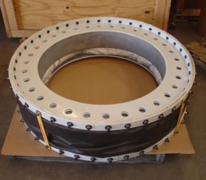
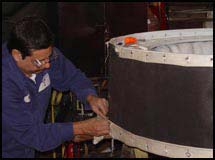
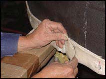
This 36″ diameter fabric expansion joint with a three-layer fabric belt includes 150 lb. flat face flanges with carbon steel backing bars and liner. The fabric belt consists of silical fabric, fiberglass fabric and mineral wool insulation. The photos below show the process of stitching the fabric belt on the first layer.
 |
 |
Inlet Details
|
Outlet Details
|
 |
|
|
 |
 |
 |
|
27″ Single Hinged |
31″ Single Hinged |
25″ Universal Expansion Joint |
Refractory Lining |
Read MoreU.S. Bellows, Inc. designed and fabricated refractory lined single-hinged and universal expansion joints for a design pressure of 75.4 PSIG and 1400°F temperature. Each expansion joint was 100% x-ray tested along the weld seems and pneumatically tested to 83 PSIG.
|
|
|
US Bellows designed and fabricated several single and universal expansion joints for a 12″ pipe size. The single joint has an axial movement of 1 3/8″ and the universal joint has a 2 1/2″ lateral movement. The design pressure is 276 PSIG, and the design temperature is 626°F.

Both single and universal expansion joints have 316L SS bellows, flanges, and tie rods. These expansion joints have 300-pound raised-face stainless steel flanges and are designed to accommodate the customers’ low spring rate requirements. Each expansion joint was 100% dye-penetrant tested and hydro-tested at 414 PSIG. US Bellows completed this expansion joint project ahead of schedule
Read More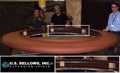
|
US Bellows designed and fabricated two 78″ I.D. x 110″ O.D. and two 36″ I.D. x 68″ O.D. thick wall flanged and flued head expansion joints. All four expansion joints were fabricated from 1/4″ thick ASTM A516 grade 70 carbon steel plate. The expansion joints were cold-formed and heat-treated to customer requirements. The external surface of the expansion joint was painted with one coat of shop primer. The weld ends of the expansion joint are beveled, and drainage plugs are installed in the crest of the bellows. The bellows long weld seams were 100% dye-penetrant and 100% x-ray tested. US Bellows provides 100% customer satisfaction in terms of quality and delivery.
Read More
 |
 |
|
Details:
|
Design Conditions:
|
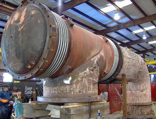
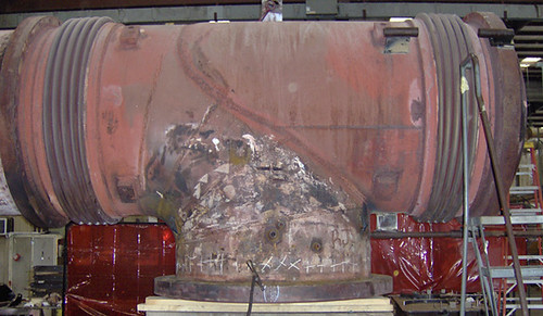

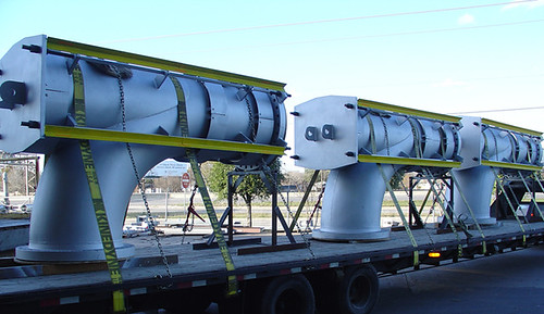
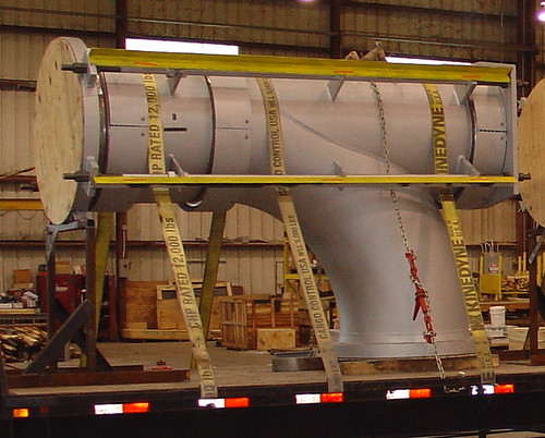
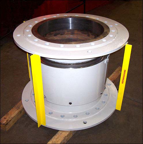
US Bellows refurbished two pressure balanced elbow expansion joints for a power generation plant with a quick turnaround during outages.
The first 54″ outside diameter expansion joint leaked from a crack in the bellows, causing an unscheduled power plant outage.
This particular expansion joint was fabricated for a high-pressure turbine crossover piping for steam service of 97 PSIG at 634°F. The 27′ long, 27,000 lb. expansion joint was refurbished in less than 4 weeks. This was made possible by utilizing dedicated employees who worked overtime six days a week. The 321 stainless steel bellows and carbon steel root rings were replaced. The outside cover bolts were removed, and new bolts were installed.
The second expansion joint was also for a high-pressure turbine that was replaced during a planned outage. This expansion joint came in on October 30, 2006 and was ready to ship November 20, 2006. The overall length and centerline-to-centerline length were maintained to ensure easy installation. Both expansion joints were dye-penetrant tested and hydro-tested at 146 PSIG.
Read More|
|
||
|
 |
 |
|
 |
This order required custom engineering to design and manufacture these expansion joints due to their critical service condition requirements. PT&P manufactured and tested these expansion joints to the customer specifications, EJMA Standards, and US Bellows Quality Standards.
Design Condition:
| 176 PSIG at 500°F | |
| 0.5 Axial Extension and 1.5 Axial Compression | |
| 18″ 304 Stainless Steel Expansion Joints with Special Designed and Machined Flange Faces with a Specially Designed Gasket Groove | |
| Special Customer Welding Requirements to A.W.S. Standards | |
| Critical Spring Rate Requirements | |
| Stringent Testing Requirements | |
| The Bellows Longitudinal Seams were 100% X-Rayed and Dye-Penetrant Examined. | |
| Each Expansion Joint was Helium Leak Tested to a Leak Rate of 1 x 10 ֿ 7 |

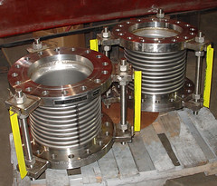
These pictures display one of many tied universal expansion joints in a large order of expansion joints designed by US Bellows for a local engineering and construction company. These expansion joints weigh 1,600 lb. each and are 10″ in diameter. They are designed for 611 PSIG and temperatures up to 180°F. These expansion joints are fabricated from 321 carbon steel pipe, tie rods and 300 lb. RF weld neck flanges. The bellows longitudinal seams were 100% x-rayed, and the complete assembly was hydro-tested to 917 PSIG to ensure a quality product and performance. The units were shipped with the mating flanges bolted to the end of the assembly.
Read More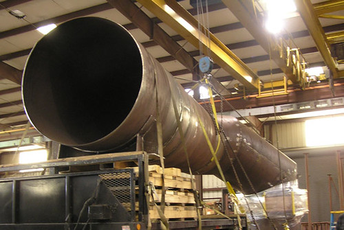
U.S. Bellows, Inc. and PT&P combined to furnish a fabric expansion joint, duct work, a spring support cradle and snubbers. US Bellows furnished a fabric expansion joint with acid resisting fabric and also a duct work measuring 34″ long and 60″ in diameter which was fabricated from ASTM A 516GR 70 carbon steel. PT&P furnished spring supports, carbon steel cradle supports, and snubbers. The expansion joint was completed within 6 weeks in time for a plant shutdown. A computerized pipe stress analysis, utilizing the Caesar II stress program, was performed to obtain the forces and moments imposed on the equipment nozzles and weights to be carried by the spring supports.
Read More |
 |
These 15 pressure relief safety valve connector expansion joints were manufactured from 316SS, A-335 P22, A-387 Gr22, A106, and A-51670. They were externally pressurized to prevent steam blowback. These externally pressurized expansion joints were attached to the relief valves in the power plant. They assist in maintaining pressure as well as provide for 7 axial and 6 lateral travel. These joints can handle applicable loads of up to 150 PSIG at 535°F and 460 PSIG at 885°F but can function if temperatures reach 1,000°F. They range from 30″ to 85″ in length and weigh between 400 lbs and 1,600 lbs. Dye penetrate, air, and soap bubble tests were completed for quality and performance assurance. |
 |
 |
These single expansion joints were fabricated from ASTM-A-240 Type 321 stainless steel bellows and liners. The shell material is ASTM-A-516 Grade 70. They are 32 diameters with an overall length of 26″. Each joint weighs 280 lbs. They were designed for 150 PSIG at 650F with a travel capacity of 0.33″ axial compression and 0.08″ lateral deflection. These expansion joints absorb differential expansion between the shell side and the tube side of a heat exchanger. |
They were hydrostatically tested to 208 PSIG to comply with the Japanese code, Ministry of Health, Labor and Welfares (MHLW), and the ASME Pressure Vessel Code Section VIII
Read More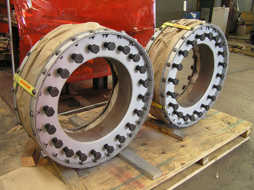
 These are 24″ diameter fabric expansion joints with an overall face to face dimension of 12″. Each expansion joint weighs 300 lb. Installed in the inlet and exhaust piping of a hot air blower, they can withstand temperatures of up to 850°F. These expansion joints were fabricated in three layers that consisted of aluminized fiberglass, ceramic fiber, and silica treated fabrics. The flanges were fabricated from carbon steel with special hex nuts welded to the inside of the bolt holes. The stud bolts are in place to assure correct alignment of the bolts to the flange bolt holes. Visual inspection and trial fitting of the stud bolts were performed to assure quality and performance.


This single expansion joint assembly was fabricated with a single-ply 304 stainless steel bellows, and carbon steel pipe, miter bends, and limit rods. It measured 12′-2″ from the center to center of the elbows. These bellows were designed with a low spring rate to meet the allowable forces and movements on the compressor inlet nozzle. All welds were air tested and spot x-rayed to assure quality and performance. This unit was completed in 3 weeks to meet the customer’s construction schedule.
Read More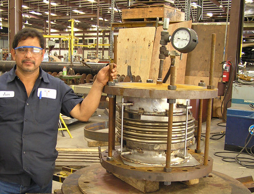
|
|
This single reinforced expansion joint is 16″ in diameter and is 15-1/8″ in length. The expansion joint is fabricated with 316L stainless steel bellows, liner, weld ends, and bellows reinforcement. This expansion joint weighs 170 lbs and is used in a feed pre-heater. It is designed and fabricated to ASME Section VIII for 581 PSIG at 842°F with a travel capacity of 0.496″ compression. 100% Dye-Penetrate testing was performed for the bellow attachment welds as well as 100% X-Ray testing on the long seam welds of the bellows and pipe ends. In addition, Hydro-testing was performed at 764 PSIG to assure quality and performance. |