


Usbellows logo.png

EJMA Logo

US Bellows is a Standards Subscriber | Exp: Dec 31, 2026 | See ejma.org to check verification process
Celebrating over 20 years of EJMA membership

The Engineer’s Guide to Refractory Selection: A Deep Dive into High-Temperature Expansion Joints

December 3, 2025

Outdoor shot of the back of an engineering manager with a helmet under his arm and a hydrogen power plant in the background.

The success of any high-temperature industrial process, from petrochemical refining to power generation, hinges on the integrity of its refractory lining. However, the aggressive thermal cycles these systems endure can subject the lining and its containment vessels to mechanical stress. This is where the workhorse of high-temperature engineering steps in: the expansion joint.

The Critical Interface: Expansion Joints and Refractory

Refractory lined expansion jointsRefractory materials, typically ceramic or concrete, are designed to insulate and protect steel components from extreme heat. Yet, they possess a relatively low tensile strength and are highly susceptible to cracking and spalling when subjected to differential thermal movement.

An expansion joint, integrated into the ductwork or piping system, absorbs the axial, lateral, and angular movement caused by thermal expansion and contraction of the surrounding steel structure. By managing this movement, the expansion joint prevents stresses from being transferred directly into the brittle refractory material, thereby maintaining the system’s structural integrity and keeping the piping’s internal insulation intact.

Key Considerations in Refractory Selection

Choosing the right refractory is only half the battle; ensuring the expansion joint is compatible with the refractory and the operating environment is paramount. Here are the factors an engineer must consider:

  • Maximum Operating Temperature: This dictates the material for both the refractory and the metallic or fabric expansion joint elements. The insulation thickness will also determine the temperature of the piping and the bellows. 
  • Refractory thickness Trade-off: A thicker refractory lowers piping temperature, allowing the use of cheaper steels such as Carbon steel; however, the piping will be heavier, requiring larger loads and supports. A thinner refractory will yield a higher shell temperature, and the use of stainless steel or alloys for the piping will lower the pipeline’s weight.
  • Chemical Environment: The presence of corrosive gases (such as SOx or NOx) or particulate matter can lead to premature degradation, requiring specialized alloys or fabric coatings, as well as abrasion-resistant refractories
  • Thermal Expansion Coefficient: Understanding the difference in expansion rates between the steel duct, the refractory material, and the expansion joint’s liner and bellows is crucial for designing the correct gap and insulation scheme.
  • Vibration and Fatigue: Systems with high flow rates or cycling operations require bellows designed to withstand the resulting fatigue stress. Vibration may be an issue for refractory, potentially leading to cracking if not accounted for during design.

Protecting the Heat: Integrating Expansion Joints 

Mastering Movement: How Expansion Joint Design Preserves Refractory Integrity

The biggest threat to a refractory-lined pipe is the uncontrolled force generated by the thermal expansion of the surrounding steel ductwork. A properly selected and installed expansion joint acts as a pressure-relief valve for mechanical stress, thereby directly extending the service life of the refractory and the piping system.

The Essential Role of Liners and Internal Insulation

The protection of the expansion joint itself is critical. High-temperature metal bellows are often protected internally by a flow liner and refractory insulation.

The flow liner serves a dual purpose: it smooths the flow of media past the bellows, reducing turbulence and vibration-induced fatigue, and it acts as a mechanical barrier to the internal insulation. This internal insulation, often ceramic fiber or a castable refractory material, shields the bellows material from the highest process temperatures. The liner must be designed to allow the bellows to move freely without compromising the insulation’s integrity during the line’s thermal cycling. 

This reduction in thermal gradient is critical, as it allows the use of lower-temperature-rated bellows alloys, which are better suited for cyclic operation due to improved cycle life, without the creep phenomenon becoming an issue under constant stress on the bellows. Without this integrated protection, the bellows would be subjected to higher temperatures and operate in the bellows material’s creep range, leading to premature failure.

US Bellows: Your Partner in Customization 

At US Bellows, we specialize in custom, refractory-lined, high-temperature expansion joints that are pre-engineered to match the thermal expansion coefficients and chemical composition of your specific refractory system. Our custom solutions minimize stress transfer, virtually eliminate refractory spalling, and drastically reduce the costly downtime associated with high-temperature system failure, providing you with predictable, sustained operational success.

Stop settling for generic solutions that fail under the heat. Contact a US Bellows high-temperature specialist today to design a refractory-matched expansion joint solution that guarantees the maximum service life for your critical assets.

Read More
Inspection During and Immediately After System Pressure Tests

May 2, 2019

WARNING: EXTREME CARE MUST BE EXERCISED WHILE INSPECTING ANY PRESSURIZED SYSTEM OR COMPONENT.

A visual inspection of the system shall include checking for the following.

  • Evidence of leakage or loss of pressure.

  • Distortion or yielding of anchors, pipe expansion joint hardware, the bellows, and other piping components.

  • Any unanticipated movement of the piping due to pressure.Evidence of instability (squirm) in the bellows.

  • The guides, pipe expansion joints, and other moveable parts of the system shall be inspected for evidence of binding.

  • Any evidence of abnormality or damage shall be reviewed and evaluated by a competent design authority.

Click on a section link below:

Read More

Installation Instructions (Summary)

April 4, 2019

Expansion Joint Installation & Maintenance Guide

The necessary steps for installing all expansion joints shall be pre-planned. The installers shall be made aware of these steps as well as the special instructions furnished with the expansion joint by the manufacturer, which will provide information necessary for proper handling and installation of expansion joints. The most critical phases of the expansion joint installation are as follows:

  1. Care shall be exercised to prevent any damage to the thin bellows section, such as dents, scores, arc strikes and weld splatter. No movement of the expansion joint (compression, extension, lateral offset, rotation) due to piping misalignment, for example, shall be imposed which has not been anticipated and designed into the movement capability of the expansion joint. Imposing such movements can result in systems malfunction or damage to the bellows or other components in the system. Specifically, cycle life can be substantially reduced, forces imposed on adjacent equipment may exceed their design limits, internal sleeve clearances may be adversely affected, and the pressure capacity and stability of the bellows may be reduced. Any field pre-positioning shall be performed in accordance with specific instructions, which include both the direction and magnitude of movement. Anchors, guides, and pipe supports shall be installed in strict accordance with the piping systems drawings. Any field variances from planned installation may affect the proper functioning of the expansion joint and must be brought to the attention of competent design authority for resolution. The expansion joint, if provided with internal sleeves, shall be installed with the proper orientation with respect to flow direction.
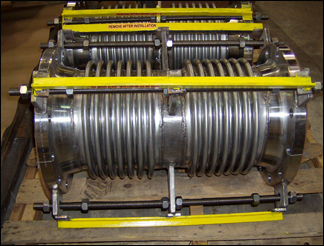
  2. Once the pipeline anchors or other fixed points are in place, the piping is properly supported and guided and the expansion joint installed, the shipping devices (usually yellow in color) should be removed in order to allow the expansion joint to compensate for changes in ambient temperature during the remainder of the construction phase.

Post Installation Inspection Prior to System Pressure Test

A careful inspection of the entire piping system shall be made with particular emphasis on the following:

  1. Are anchors, guides, and supports installed in accordance with the system drawings? Is the proper expansion joint in the proper location? Are the expansion joint flow direction and pre-positioning correct? Have all of the expansion joint shipping devices been removed? If the system has been designed for gas and is to be tested with water, has provision been made for proper support of the additional dead weight load on the piping and expansion joint? Are all guides, pipe supports, and the expansion joint free to permit pipe movement? Are any expansion joint misaligned? This can be determined by measuring the joint overall length, an inspection of the convolution geometry, and checking clearances at critical points on the expansion joint and at other points in the system.
  2. Are the bellows and other movable portions of the expansion joint free of foreign material?

WARNING: Extreme care must be exercised while inspecting any pressurized system or component.

Inspection During and After System Pressure Tests

A visual inspection of the system shall include checking any pressurized system or component for:

  1. Evidence of leakage or loss of pressure, distortion or yielding of anchors, expansion joints hardware, the bellows, and other piping components. Any unanticipated movement of the piping due to pressure evidence of instability (squirm) in the bellows. The guides, expansion joints, and other movable parts of the system shall be inspected for evidence of binding.
  2. Any evidence of abnormality or damage shall be reviewed and evaluated by competent design authority.

Periodic In-Service Inspections

Immediately after placing the system in operation, a visual inspection shall be conducted to ensure that the thermal expansion is being absorbed by the Expansion Joints in the manner for which they were designed. The bellows shall be inspected for evidence of unanticipated vibration. A program of periodic inspection shall be planned by the system designer and conducted throughout the operating life of the system. The frequency of this inspection will be determined by the service and environmental conditions involved. These inspections shall include the items in the 2 inspection lists above, as well as an examination for signs of external corrosion, loosening of threaded fasteners and deterioration of anchors, guides, and other hardware. IT MUST BE UNDERSTOOD THAT THIS INSPECTION PROGRAM, WITHOUT ANY OTHER BACKUP INFORMATION, CANNOT GIVE EVIDENCE OF DAMAGE DUE TO FATIGUE, STRESS CORROSION OR GENERAL INTERNAL CORROSION. THESE CAN BE THE CAUSE OF SUDDEN FAILURES AND GENERALLY OCCUR WITHOUT ANY VISIBLE OR AUDIBLE WARNING. Where the critical nature of the system warrants, it may be necessary to devise means for minimizing the probability of this type of failure, including periodic preventive replacement of critical system components. When any inspection reveals evidence of malfunction, damage, or deterioration, this shall be reviewed by competent design authority for resolution.

System Operation

A record shall be maintained of any changes in system operation conditions (such as pressure, temperature, thermal cycling, water treatment, and piping modifications. Any such change shall be reviewed by the competent design authority to determine its effect on the performance of the anchors, guides, and expansion joint.

Causes of Failures

Bellows expansion joints will give many years of satisfactory service when they are properly designed and manufactured for specified piping system conditions. Failures can occur for many reasons, but experience has shown that certain causes of failure fall into distinct categories.
The following are some typical causes:

  1. Shipping and handling damage. Examples:
    1. Denting or gouging of bellows from being struck by hard objects (tools, chain falls, forklifts, adjacent structures, etc.). Improper stacking for shipping or storage.
    2. Insufficient protection from weather or other adverse environmental conditions.
  2. Improper installation and insufficient protection during and after installation. Examples:
    1. Direction with respect to flow. Joints with internal liners installed in reverse. Installing a joint in a location other than as prescribed by the installation drawings. Premature removal of shipping devices. Springing of bellows to make up for piping misalignment. Insufficient protection from mechanical damage due to work in the surrounding area. Insufficient protection of bellows during a nearby welding operation. Failure to remove shipping devices before system operation. Improper anchoring, guiding supporting of the piping system.
    2. Anchor failure in service.
  3. Bellows corrosion. Examples:
    1. Improper selection of bellows material for the flowing medium and/or adverse external environment. Specifically, chlorides leaching from insulation, have been frequently the causes of stainless steel bellows corrosion.
    2. Stress corrosion cracking (consult the material manufacturer for proper selection).
  4. System over-pressurization (in-service or hydro test). Bellows vibration (mechanical or flow-induced) resulting in fatigue failure. Excessive bellows movement (axial, lateral, and angular movement greater than design values). Bellows erosion. Example:
    1. Bellows without internal liner installed in a system having a very high velocity and/or erosive flowing medium.
    2. Packing of particulate matter in bellows convolutions which inhibits proper movement of the bellows.

Expansion Joints: Do’s and Don’ts

From the “Standards of the Expansion Joint Manufacturers Association, Inc”

Do’s

Don’ts

  • Inspect for damage during shipment, i.e., dents, broken hardware, watermarks on the carton, etc.
  • Store in a clean dry area where it will not be exposed to heavy traffic or damaging environment.
  • Use only designated lifting lugs.
  • Make the piping systems fit the expansion joint. By stretching, compressing, or offsetting the joint to fit the piping, the joint may be overstressed when the system is in service.
  • It is good practice to leave one flange loose until the expansion joint has been fitted into position.
  • Make necessary adjustment of loose flange before welding.
  • Install joint with the arrow pointing in the direction of flow.
  • Install single Van stone liners, pointing in the direction of flow.
  • Be sure to install a gasket between the mating flange and liner.
  • With telescoping Van stone liners, install the smallest I.D. liner pointing in the direction of flow.
  • Remove all shipping devices after the installation is complete and before any pressure test of the fully installed system.
  • Remove any foreign material that may have become lodged between the convolutions.
  • Do not drop or strike carton.
  • Do not remove shipping bars until installation is complete.
  • Do not remove any moisture-absorbing desiccant bags or protective coatings until ready for installation.
  • Do not use hanger lugs as lifting lugs without the approval of the manufacturer.
  • Do not use chains or any lifting device directly on the bellows or bellows cover.
  • Do not allow weld splatter to hit unprotected bellows. Protect with wet chloride-free insulation.
  • Do not use cleaning agents that contain chlorides.
  • Do not use steel wool or wire brushes on bellows.
  • Do not force-rotate one end of an expansion joint for alignment of bolt holes. Ordinary bellows are not capable of absorbing torque.
  • Do not hydrostatic pressure test or evacuate the system before installation of all guides and anchors. Pipe hangers are not adequate guides.
  • Do not exceed a pressure test 1-½ times the rated working pressure of the expansion joint.
  • Do not use shipping bars to retain thrust if tested prior to installation.

Refer to EJMA Standard for proper guide spacing and anchor recommendations.
NOTE: The manufacturer’s warranty may be void if improper installation procedures have been used.

Click on a section link below:

Read More

System Operations

A record shall be maintained of any changes in system operating conditions (i.e. pressure, temperature, thermal cycling, water treatment) and piping modifications. Any such change shall be reviewed by the competent design authority to determine its effect on the performance of the anchor, guides, and pipe expansion joints.

Click on a section link below:

Read More

Installation Misalignment

During the erection of piping systems, the accuracy of the location of equipment, pipe supports, structure and the piping itself is never perfect. Since the pipe expansion joint is usually far more easily deflected than any of these other components, it is tempting for piping installers to use it to correct for misalignment. The installation instructions of PT&P’s pipe expansion joints, as well as other manufacturers, require that the piping is aligned to the pipe expansion joint during installation. The pipe expansion joints will arrive from the factory with rigid restraints which maintain their length and ends in the position and dimensions of the specification in this catalog.

If some misalignment must be accepted by the pipe expansion joint, this can be accommodated by the addition of devices such as limit rods which can be used during the installation to adjust the pipe expansion joints to fit. Any proposed misalignment should be clearly stated to PT&P so that the amount of deflection possible can be considered in the total deflection capability of the proper selection. As an example, one would not want to have a needed cyclic axial compression capability of 0.5 inch (12.7 mm) cut in half by compression due to pipe misalignment of .025 inch (6.4 mm).

Bellows Squirm

Bellows Squirm


Click on a section link below:

Read More

Typical Causes of Failure

Knowing and being able to identify common causes of expansion joint damage is vital for industrial safety. A metallic expansion bellows typically fails due to improper installation, upset events (overpressurization), unforeseen system shifts, improper anchoring/guiding, or corrosion from harsh media.

Early detection of these metallic bellows failure modes helps prevent operational downtime.

Typical Causes of Expansion Joint Failure

Understanding and Preventing Metallic Expansion Joint Failure

Metallic expansion joints, are integral components in piping infrastructure and are designed to absorb movement and vibration. They can fail if not handled, installed, and maintained correctly. 

The Expansion Joint Manufacturing Association (EJMA) recommends regular inspections of expansion joints as part of a proactive maintenance program for best performance and a longer lifespan. 

No matter how well-built they are, though, time will eventually catch up with them. Eventually, your expansion joints, custom-built for your piping system, will fail. 

If not addressed, this expansion joint failure will escalate, damaging surrounding equipment and necessitating a shutdown that can result in significant financial and manpower costs for your company. As such, the first step in protecting your expansion joints is to be aware of how they can fail. 

Failures can happen for many reasons. However, experience shows that some causes of failure fit into clear categories.

Common Expansion Joint Failures

This list shows some common causes of failure:

  • Shipping and handling damage. Examples: Denting or gouging of bellows from being struck by hard objects (tools, chain falls, forklifts, adjacent structures, etc.); improper stacking for shipping or storage; insufficient protection from weather or other adverse environmental conditions.

  • Improper installation and insufficient protection

    • During and after installation

    • Examples: Joints with internal liners installed in the reverse direction with respect to flow; installing a pipe expansion joint in a location other than as prescribed by the installation drawings; premature removal of shipping devices; springing of bellows to make up for piping misalignment; insufficient protection from mechanical damage due to work in the surrounding area; insufficient protection of bellows during nearby welding operations and failure to remove shipping devices before placing system in operation.

  • Improper anchoring, guiding and supporting of the system

  • Anchor failure in service

  • Bellows corrosion, both internal and external

  • System over-pressure (in-service or hydro test) and bellows vibration (mechanical or flow induced resulting in high cycle fatigue)

  • Excessive bellows deflection (axial, lateral, angular deflections greater than design values)

  • Torsion

  • Bellows erosion

  • Packing of particulate matter in the bellows convolutions which inhibits proper movement of the bellows.

Expansion joint failures are not just a concern for users, but manufacturers as well. US Bellows’ job does not end once we ship a joint; it continues long after as we provide support and assistance to prevent failures such as these. 

Knowing how to identify failures in expansion joints in the first step to fixing it. By working with us, you can learn the right solutions and prevent issues before they cause a complete stop in your piping system.

Need help knowing when to replace your expansion joints? Download our Expansion Joint Checklist or FAQ for more information.

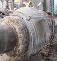
A photo example of over-pressurization present in a 48" pipe expansion joint
Over Pressurization of a 48″ Pipe Expansion Joint


A photo example of over-pressurization present in an installed pipe expansion joint
Over Pressurization of Pipe Expansion Joint


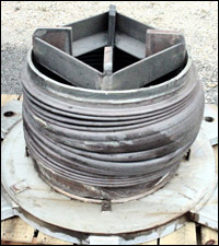
A photo example of over-pressurization present in an uninstalled pipe expansion joint
Over Pressurization of Pipe Expansion Joint

Click on a section link below:


Did you know that US Bellows is a Piping Technology Company?

We are proud to be a one-stop solution from expansion joints to pipe supports and engineering services. We work hard to simplify your supply chain, and ensure system reliability with quality assurance.

Read More

Post-Installation Inspection

 A careful inspection of the entire piping system shall be made with particular emphasis on the following.

    • Are the anchors, guides, and supports installed in accordance with the system drawings?

    • Is the proper pipe expansion joint in the proper location?

    • Are the pipe expansion joint flow direction and positioning correct?

    • Have all the pipe expansion joint shipping devices been removed?

    • Are all guides, pipe supports, and the pipe expansion joints free to permit pipe movement?

    • If the system has been designed for gas and is to be tested with water, have provisions been made for proper support of the additional dead weight load on the piping and pipe expansion joint? Some water may remain in the bellows convolutions after the test. If this is detrimental to the bellows or system operation, means shall be provided to remove such water.

    • Has any pipe expansion joint been damaged during handling and installation?

    • Is any pipe expansion joint misaligned? This can be determined by measuring the pipe expansion joints’ overall length, an inspection of the convolution geometry, and checking clearances at critical points on the pipe expansion joint and at other points in the system.

    • Are the bellows and other movable portions of the pipe expansion joint free of foreign material?

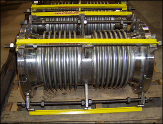
Expansion Joints with Shipping Bars
Pipe Expansion Joints with Shipping Bars that Must be Removed Post Installation

Click on a section link below:

Read More

Post-Installation Inspection

A careful inspection of the entire piping system shall be made with particular emphasis on the following.

  • Are the anchors, guides and supports installed in accordance with the system drawings?

  • Is the proper pipe expansion joint in the proper location?

  • Are the pipe expansion joint flow direction and positioning correct?

  • Have all the pipe expansion joint shipping devices been removed?

  • Are all guides, pipe supports and the pipe expansion joints free to permit pipe movement?

  • If the system has been designed for a gas, and is to be tested with water, have provisions been made for proper support of the additional dead weight load on the piping and pipe expansion joint? Some water may remain in the bellows convolutions after the test. If this is detrimental to the bellows or system operation, means shall be provided to remove such water.

  • Has any pipe expansion joint been damaged during handling and installation?

  • Is any pipe expansion joint misaligned? This can be determined by measuring the pipe expansion joints’ overall length, inspection of the convolution geometry, and checking clearances at critical points on the pipe expansion joint and at other points in the system.

  • Are the bellows and other movable portions of the pipe expansion joint free of foreign material?

Expansion Joints with Shipping Bars
Pipe Expansion Joints with Shipping Bars that Must be Removed Post Installation
Read More

Installation and Maintenance Guide


Pipe Expansion Joints: Do’s and Don’ts  From the “Standards of the Expansion Joint Manufacturers Association, Inc”

Do’s

Dont’s

  • Inspect for damage during shipment, i.e., dents, broken hardware, watermarks on the carton, etc.
  • Store in a clean dry area where it will not be exposed to heavy traffic or damaging environment.
  • Use only designated lifting lugs.
  • Make the piping systems fit the expansion joint. By stretching, compressing, or offsetting the joint to fit the piping, the joint may be overstressed when the system is in service.
  • It is good practice to leave one flange loose until the expansion joint has been fitted into position. Make necessary adjustments to the loose flange before welding.
  • Install joint with the arrow pointing in the direction of flow.
  • Install single Van stone liners, pointing in the direction of flow. Be sure to install a gasket between the mating flange and liner.
  • With telescoping Van stone liners, install the smallest I.D. liner pointing in the direction of flow.
  • Remove all shipping devices after the installation is complete and before any pressure test of the fully installed system.
  • Remove any foreign material that may have become lodged between the convolutions.
  • Refer to EJMA Standards for proper guide spacing and anchor recommendations.
  • Do not drop or strike the carton.
  • Do not remove shipping bars until installation is complete.
  • Do not remove any moisture-absorbing desiccant bags or protective coatings until ready for installation.
  • Do not use hanger lugs as lifting lugs without the approval of the manufacturer.
  • Do not use chains or any lifting device directly on the bellows or bellows cover.
  • Do not allow weld splatter to hit unprotected bellows. Protect with wet chloride-free insulation.
  • Do not use cleaning agents that contain chlorides.
  • Do not use steel wool or wire brushes on bellows.
  • Do not force-rotate one end of an expansion joint for the alignment of bolt holes. Ordinary bellows are not capable of absorbing torque.
  • Do not hydrostatic pressure test or evacuate the system before the installation of all guides and anchors. Pipe hangers are not adequate guides.
  • Do not exceed a pressure test 1-½ times the rated working pressure of the expansion joint.
  • Do not use shipping bars to retain thrust if tested prior to installation.
  • Pipe hangers are not adequate guides.

Refer to EJMA Standard for proper guide spacing and anchor recommendations.
NOTE: The manufacturer’s warranty may be void if improper installation procedures have been used.

Read More

Installation & Maintenance (Metallic Expansion Joints)

October 5, 2017

Click on a section link below:


Pipe Expansion Joints: Do’s and Don’ts: From the “Standards of the Expansion Joint Manufacturers Association, Inc”

Do’s

Don’ts

  • Inspect for damage during shipment, i.e., dents, broken hardware, watermarks on the carton, etc.
  • Store in a clean dry area where it will not be exposed to heavy traffic or damaging environment.
  • Use only designated lifting lugs.
  • Make the piping systems fit the expansion joint. By stretching, compressing, or offsetting the joint to fit the piping, the joint may be overstressed when the system is in service.
  • It is good practice to leave one flange loose until the expansion joint has been fitted into position. Make necessary adjustment of loose flange before welding.
  • Install joint with an arrow pointing in the direction of flow.
  • Install single Van stone liners, pointing in the direction of flow. Be sure to install a gasket between the mating flange and liner.
  • With telescoping Van stone liners, install the smallest I.D. liner pointing in the direction of flow.
  • Remove all shipping devices after the installation is complete and before any pressure test of the fully installed system.
  • Remove any foreign material that may have become lodged between the convolutions.
  • Refer to EJMA Standards for proper guide spacing and anchor recommendations.
  • Do not drop or strike carton.
  • Do not remove shipping bars until installation is complete.
  • Do not remove any moisture-absorbing desiccant bags or protective coatings until ready for installation.
  • Do not use hanger lugs as lifting lugs without the approval of the manufacturer.
  • Do not use chains or any lifting device directly on the bellows or bellows cover.
  • Do not allow weld splatter to hit unprotected bellows. Protect with wet chloride-free insulation.
  • Do not use cleaning agents that contain chlorides.
  • Do not use steel wool or wire brushes on bellows.
  • Do not force-rotate one end of an expansion joint for alignment of bolt holes. Ordinary bellows are not capable of absorbing torque.
  • Do not hydrostatic pressure test or evacuate the system before installation of all guides and anchors. Pipe hangers are not adequate guides.
  • Do not exceed a pressure test 1-½ times the rated working pressure of the expansion joint.
  • Do not use shipping bars to retain thrust if tested prior to installation.
  • Pipe hangers are not adequate guides.

Refer to EJMA Standard for proper guide spacing and anchor recommendations.
NOTE: The manufacturer’s warranty may be void if improper installation procedures have been used.

Read More