Safeguarding Your System: Proactive Metal Expansion Joint Maintenance & Turnaround Planning
In the interconnected environment of industrial operations, where high temperatures, extreme pressures, and corrosive media are the norm, certain components silently bear the brunt of the forces at play. Among these durable components, metal expansion joints are a notable example. These flexible elements are designed to absorb movement, vibration, and thermal expansion within piping systems, preventing stress buildup that could otherwise lead to catastrophic failures. Yet, despite their critical role, expansion joints are often overlooked until a problem arises, leading to costly emergency repairs and unscheduled downtime.
This guide explores the key strategies for proactive maintenance and meticulous turnaround planning of metal expansion joints. By understanding their function, recognizing common failure modes, and implementing an inspection and replacement program, you can significantly enhance the reliability of your entire piping infrastructure.
The Crucial Role of Metal Expansion Joints: More Than Just a Flex Point
Before we dive into maintenance, let’s understand why expansion joints are so critical. Imagine a rigid piping system subjected to extreme temperature fluctuations. As the pipe heats up, it expands; as it cools, it contracts. If the pipes are fixed at the ends and lack a flexible element to accommodate thermal movement, immense stresses would buildup, leading to buckling, cracking, and eventual failure of the pipes, flanges, or connected equipment such as pumps and turbines.
Metal expansion joints, typically fabricated from corrugated metal bellows, are specifically engineered to:
- Absorb Thermal Movement: They compensate for axial (along the pipe’s axis), lateral (perpendicular to the axis), and angular (rotational) movements caused by temperature changes.
- Isolate Vibration: They can prevent the transmission of mechanical vibrations from rotating equipment (pumps, compressors) to the rest of the piping system, reducing noise and fatigue.
- Accommodate Misalignment: They can absorb minor misalignments in piping runs that occur during installation or due to settling.
- Relieve Mechanical Stress: By providing flexibility, they protect sensitive equipment from stresses induced by pipe movement, and when coupled with tie-rods or hinges, they can also retain the pressure thrust.
Without properly functioning expansion joints, the integrity of your entire system is compromised, leading to safety incidents, environmental releases, and financial losses.
Understanding Expansion Joint Design and Types for Informed Maintenance
To effectively maintain expansion joints, it is essential to understand their basic design principles and the common types encountered in industrial applications.
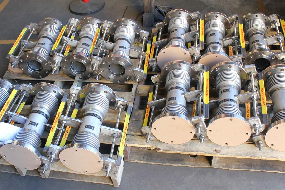
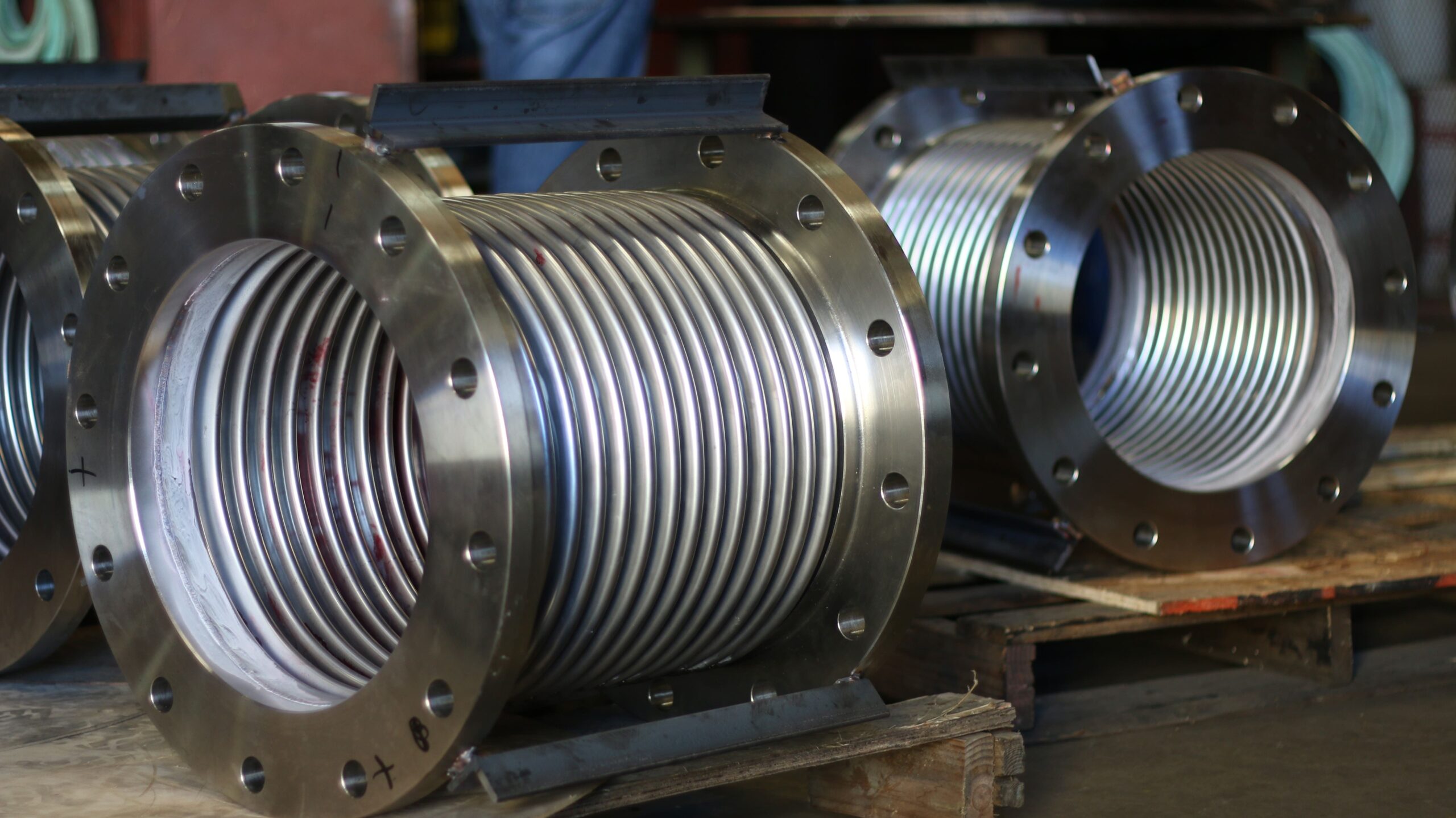
- Bellows: The heart of the expansion joint, typically made from thin-gauge stainless steel alloys (e.g., 304, 316, Inconel-625), formed into a series of convolutions (ridges and valleys). The number and depth of convolutions determine the joint’s flexibility and movement capacity.
- End Fittings: Flanges, weld ends, or threaded connections that connect the bellows to the piping system.
- Liners (Internal Sleeves): Used to reduce flow turbulence, prevent abrasion from solid particles, and protect the bellows from flow-induced vibration.
- Covers (External): Protect the delicate bellows from external damage, weld splatter, installation damage, and mechanical impact.
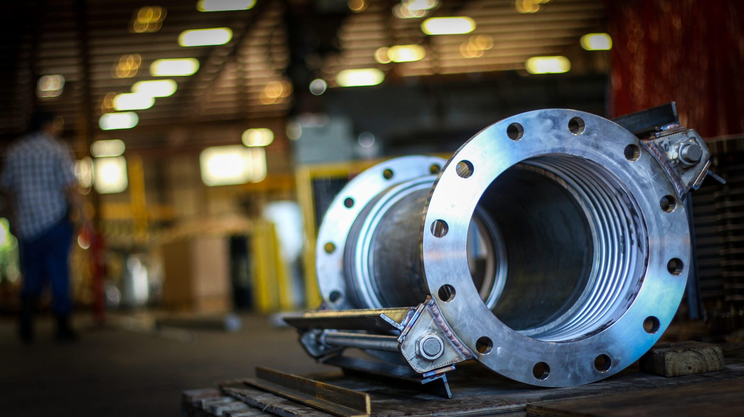
- Hardware (Tied Rods, Limit Rods, Gimbals, Hinges): These external components are crucial for controlling and distributing movement, restraining pressure thrust, and preventing over-extension or compression of the bellows.
- Tie Rods: Restrain pressure thrust while allowing lateral and angular movement.
- Limit Rods: Allow for axial movement (extension/compression) but prevent over-extension or over-compression beyond design limits.
- Hinged Joints: Allow angular movement in a single plane.
- Gimbal Joints: Allow angular movement in any plane.
- Universal Joints: Consist of two bellows and a central pipe section, designed to absorb large lateral movements.
Each type has specific maintenance considerations, particularly regarding the condition of its external hardware, which directly influences its ability to perform its designed function.
The Pitfalls: Common Failure Modes of Metal Expansion Joints
Understanding how expansion joints fail is the first step toward preventing them. Most failures are not sudden but rather a culmination of prolonged stress, improper installation, or environmental degradation.
- Fatigue Failure: This is the most common failure mode, typically manifesting as cracking in the bellows convolutions. It results from repeated cycling of the bellows beyond its design limits or from excessive vibration. Factors contributing to fatigue include:
- Over-extension/Over-compression: Movement exceeding the specified design limits.
- Lateral Misalignment: Excessive sideways movement.
- Vibration: Low-frequency, high-amplitude vibrations are especially detrimental to metal expansion joints.
- Improper Guiding & Anchoring: Insufficient pipe guides and anchors can result in unsupported pipe sections and unguided thermal movement, leading to buckling of the expansion joint.
- Corrosion:
- External Corrosion: Exposure to aggressive atmospheric conditions, chemical spills, or insulation leaching can cause the bellows’ external surface to corrode.
- Internal Corrosion: Attack by the transported media (e.g., acids, chlorides) can thin the bellows material, leading to pinholes or cracks. This is often exacerbated by stagnant flow or condensate buildup in the convolutions.
- Stress Corrosion Cracking (SCC): A particularly insidious form of corrosion where specific environmental conditions (e.g., chlorides, sulfur compounds) combine with tensile stress to cause cracking, even in otherwise resistant alloys.
- Mechanical Damage:
- Puncture/Abrasion: External impact during installation, maintenance, or operation (e.g., dropped tools, weld splatter, falling debris). These can dent the bellows, acting as stress risers and a potential failure point.
- Flow Erosion: High-velocity abrasive media (e.g., slurries) or excessive turbulence can erode the internal surface of the bellows, especially if a liner is absent or damaged.
- Flange & Weld Failures: Less common for the bellows itself, but failures can occur at the attachment points due to poor welding, excessive stress, or improper bolting.
- Improper Installation: This is a leading cause of premature failure. Issues include:
- Installation Misalignment: Forcing the joint into position can lead to permanent pre-stress.
- Lack of Proper Pre-Set: Some joints are designed with a specific pre-compression or pre-extension to achieve optimal performance at operating temperatures.
- Inadequate Pipe Support, Guides, and Anchors: The expansion joint relies heavily on the surrounding pipe infrastructure to function correctly. Without proper guidance and anchorage, the joint can experience unexpected movements and stresses.
- External Damage: Damaging the bellow during handling and installation.
- Galling of Tie Rods/Hardware: If tie rods or limit rods are seized, they can restrict the intended movement, leading to over-stressing of the bellows. If the tie-rods are corroded, they can break loose and cause over-extension/compression of the bellows, as well as potential mechanical damage from the pressure thrust.
- Upset events: System over-pressurization, pressure surges, upset conditions exceeding the expansion joint limits, or an increase in media velocity/conditions without consulting the manufacturer.
The Maintenance Imperative: Developing a Proactive Inspection Program
An inspection program is the cornerstone of effective maintenance for expansion joints. This isn’t just about identifying failures; it’s about predicting and preventing them.
Routine Visual Inspections (Operating Conditions)
These quick checks should be integrated into regular plant rounds and conducted by operations or maintenance personnel familiar with the system.
- Tie Rod/Limit Rod Condition: Are they straight? Free to move? Signs of corrosion or seizing? Are nuts loose and out of position?
- Alignment: Any obvious signs of pipe misalignment leading into or out of the joint.
- Pipe Support Integrity: Are adjacent pipe supports and guides intact and functioning properly? Sagging pipes or damaged guides can transfer excessive loads to the expansion joint.
- Evidence of Movement: Mark the initial position of tie rods or bellows convolutions relative to a fixed point. During inspections, verify that the actual movement falls within the expected range for the operating conditions.
- Foreign Material: Accumulation of debris, insulation fibers, or chemical residue on the bellows.
In-Depth Inspections (During Shutdowns/Turnarounds)
These are more thorough inspections conducted when the system is depressurized, de-energized, and cooled down (or at ambient temperature). This is where detailed assessment and planning for replacements occur.
- Frequency: Quarterly, or after any significant system upset (e.g., emergency shutdown, pressure spike).
- What to Look For:
- Obvious Signs of Leakage: Staining, drips, or puddles around the bellows or end connections.
- External Damage: Dents, gouges, scratches, or corrosion on the bellows or cover.
- Distortion of Bellows: Bulging, flattening, or unusual deformation of convolutions.
- Tie Rod/Limit Rod Condition: Are they straight? Free to move? Signs of corrosion or seizing? Are nuts loose and out of position?
- Alignment: Any obvious signs of pipe misalignment leading into or out of the joint.
- Pipe Support Integrity: Are adjacent pipe supports and guides intact and functioning properly? Sagging pipes or damaged guides can transfer excessive loads to the expansion joint.
- Evidence of Movement: Mark the initial position of tie rods or bellows convolutions relative to a fixed point. During inspections, verify that the actual movement falls within the expected range for the operating conditions.
- Foreign Material: Accumulation of debris, insulation fibers, or chemical residue on the bellows.
In-Depth Inspections (During Shutdowns/Turnarounds)
These are more thorough inspections conducted when the system is depressurized, de-energized, and cooled down (or at ambient temperature). This is where detailed assessment and planning for replacements occur.
- Frequency: Typically during every planned shutdown or turnaround (1-5 years, depending on service severity).
- What to Look For (in addition to routine checks):
- Internal Inspection (if possible): If the line is open, visually inspect the bellows’ internal surface for corrosion, erosion, or liner damage. This is particularly crucial for abrasive or highly corrosive services.
- Dye Penetrant or Magnetic Particle Testing: For suspicious cracks or surface imperfections, NDT methods can confirm the presence and extent of defects.
- Hardware Functionality: Manually attempt to move tie rods or limit rods (if safe and possible) to ensure they are not seized. Check all bolted connections for tightness.
- Insulation & Cover Removal: Carefully remove protective covers/insulation to gain full visual access to the bellows. Reinstall properly after inspection.
- Leak testing: If the expansion joint has two plies and a testable port, perform a leak test using air or nitrogen between the plies to ensure the two plies are working correctly.
Documentation: Record detailed findings, including photographs, measurements, and recommended actions. This data is invaluable for trend analysis and future planning.
Strategic Turnaround Planning for Expansion Joint Replacement
Turnarounds are high-stakes events where meticulous planning can prevent costly overruns and delays. Expansion joint replacement should be a core component of this planning.
Pre-Turnaround Preparation: The Key to Success
- Identify Critical Spares: Based on historical data, inspection reports, and failure rates for different services, identify all expansion joints that are likely candidates for replacement.
- “Run to Failure” vs. “Proactive Replacement”: For critical services, proactive replacement based on age or condition assessment is often cheaper than emergency replacement. For less critical services, a “run to failure” strategy might be acceptable if spares are readily available.
- Detailed Scope Definition: For each identified joint, document:
- Full Specifications: Material, size, pressure rating, temperature, design movement, end fittings, and external hardware. Access original manufacturer drawings and data sheets.
- Installation Location: Line number, equipment tag, exact position.
- Access Requirements: Scaffolding, lifting equipment, hot-work permits, confined-space entry, and insulation removal.
- Procurement Lead Times: Expansion joints are often custom-engineered, which can result in longer procurement lead times. Standard lead times can range from weeks to months for specialized materials or complex designs.
- Order Well in Advance: Place orders for critical spares months before the turnaround.
- Emergency Spares: Maintain a stock of standard sizes and types for unforeseen failures or minor projects.
- Contractor Selection & Training:
- Ensure that installation contractors are experienced in handling and installing expansion joints. Improper installation is a leading cause of premature failure.
- Confirm they understand the importance of proper handling (e.g., avoiding lifting by the bellows), alignment, and torqueing of bolts.
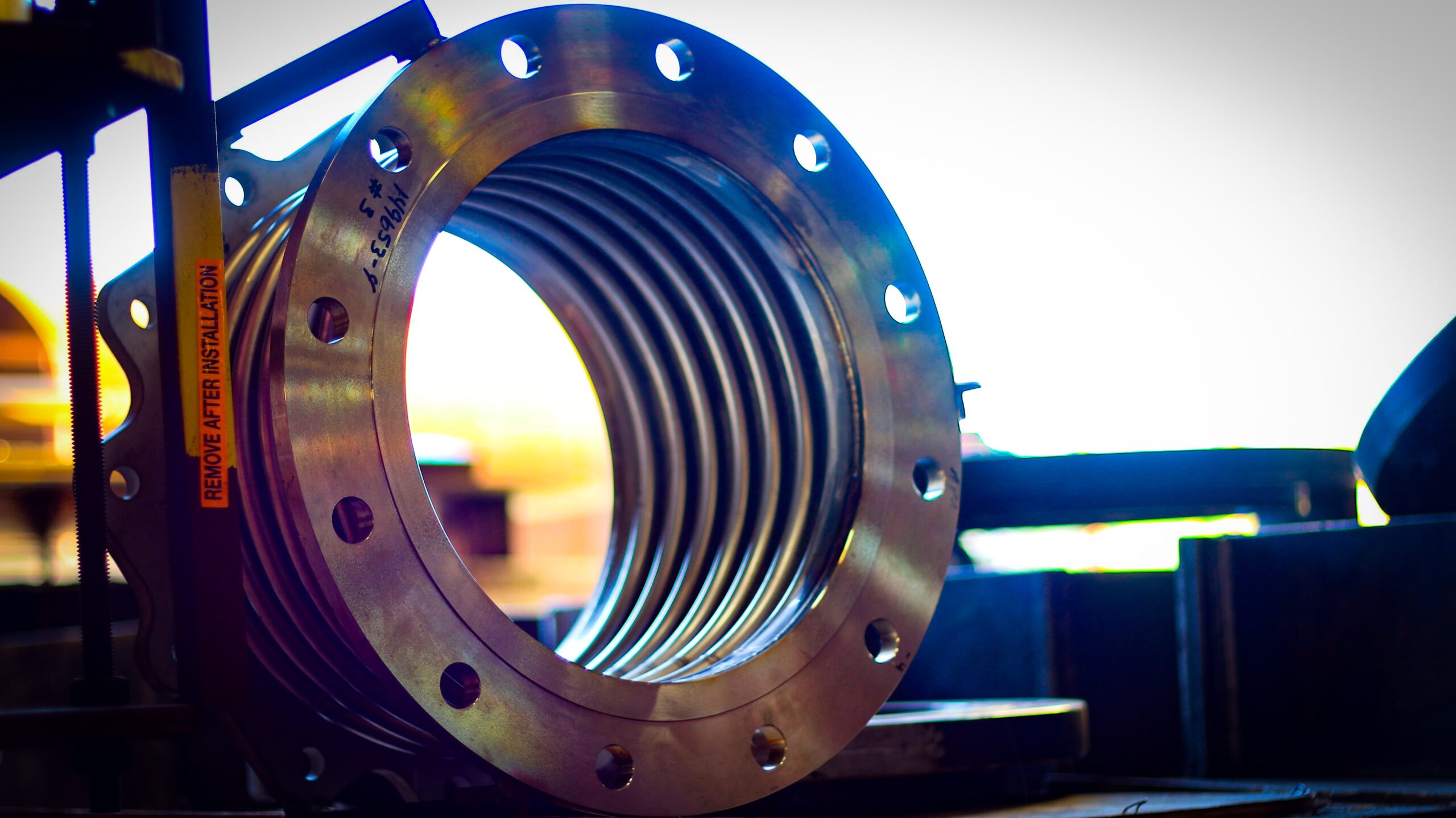
- Emphasize the importance of removing shipping restraints only after the joint is fully installed and anchored.
- Develop Detailed Work Procedures:
- Step-by-step instructions for removing old joints and installing new ones.
- Include safety precautions, required tools, bolt torque specifications, and pre-setting instructions.
- Reference applicable standards (e.g., EJMA standards for metallic bellows expansion joints).
During the Turnaround: Execution and Verification
- Safe Removal: Depressurize, drain, and decontaminate the line. Support adjacent piping before removing the old joint.
- Piping Alignment Check: Before installing the new joint, verify that the mating flanges/pipe ends are correctly aligned. Any misalignment must be corrected in the piping, not by forcing the expansion joint.
- Careful Installation:
- Handling: Never lift or support the expansion joint by the bellows itself. Use lifting lugs, end fittings, or dedicated lifting devices.
- Pre-set (if required): Ensure the expansion joint is set to the correct length, as specified by the manufacturer’s installation instructions for the applicable temperature.
- Bolting: Torque flange bolts evenly and incrementally to the specified values, using a star pattern.
- Gasket Selection: Use appropriate gaskets for the service conditions.
- Remove Shipping Restraints: CRITICALLY IMPORTANT! Shipping bars/restraints must only be removed after the expansion joint is fully installed, bolted, and the adjacent piping is properly supported and anchored. Failure to do so can lead to over-pressurization and catastrophic failure.
- Post-Installation Inspection: Visually inspect the newly installed joint for proper alignment, tight connections, and removal of all shipping hardware.
- Pressure Testing: After installation, the system will undergo pressure testing. Monitor expansion joints closely during this phase for any signs of leakage or deformation.
Post-Turnaround Follow-up: Ensuring Long-Term Reliability
- First-Run Inspection: Conduct a visual inspection shortly after the system returns to operation and reaches stable operating temperatures. Look for any unusual movement, leaks, or deformation.
- Baseline Documentation: Update plant records with installation dates, new joint specifications, and any observed conditions. This creates a new baseline for future inspections.
- Lessons Learned: Conduct a post-turnaround review to identify successes, challenges, and areas for improvement in the expansion joint maintenance and planning process.
Partner with US Bellows for Turnaround Success
At US Bellows, we don’t just fabricate expansion joints; we engineer peace of mind from the ground up.
Unlike commodity suppliers, we combine decades of American manufacturing excellence with a deep bench of in-house ASME-certified engineers who understand the complex interplay of pipe stress and environmental factors.
Our value isn’t just in the superior quality of our components, but in our proactive partnership approach: from advanced finite element analysis (FEA) to custom design for extreme conditions, rapid emergency manufacturing, and expert field service consultation.
When your system demands absolute reliability and precise engineering, US Bellows delivers a solution built to outlast, outperform, and protect your most critical assets: ensuring your turnarounds are defined by certainty, not speculation.
Is your plant’s reliability hanging by a thread? Don’t let failing expansion joints dictate your next shutdown.
Take control of your system’s integrity. Contact US Bellows today for a complimentary engineering consultation on your most critical expansion joint applications. Let our experts help you identify potential failure points, optimize your turnaround strategy, and design robust solutions that guarantee uptime and peace of mind.
Schedule your consultation and secure your system’s future.