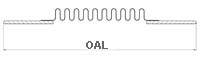
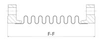
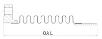
Single Expansion Joints – 38 Inch Nominal Diameter
38 Inch Nominal Diameter
Effective (Thrust) Area: 1231.38 in2 (7942.40 cm2)
Notes:
- Rated life cycle at 650°F is 3000 cycles for any one tabulated movement.
- To combine axial, lateral and angular movements, please refer to the how to order section
- To increase cycle life or movements, please refer to the graph on cycle life
- Rated bellows extension is equal to rated axial movement. Provided bellows is precompressed the amount of design extension. Installed overall length will decrease by the amount of precompression.
- Maximum test pressure: 1.5 X rated working pressure.
- Bellows rated for 650°F: For appropriate flange temperature/pressure ratings, see catalog flange data
- Torsional spring rate data provided only for modeling expansion joints on computer stress programs. Please consult factory for allowable torsional loadings.
- Overall lengths and weights for unrestrained expansion joints only. Consult factory for information regarding tied, hinged, or gimbal expansion joints.
- Pressure thrust load applied to adjacent pipe anchors/equipment when unrestrained expansion joints are used.
| Dia | Pressure | Overall Length and Weight | Non-concurrant movements | Spring rates | ||||||||||
| Flanged Ends | Weld Ends | Combination Ends | Axial | Lateral | Angular | Axial | Lateral | Angular | Torsional | |||||
| Overall Length | Weight | Overall Length | Weight | Overall Length | Weight | Compression | ||||||||
| PSIG | in. | lb. | in. | lb. | in. | lb. | in. | in. | deg. | lb./in. | lb./in. | in./lb./deg. | in./lb./deg. x 106 |
|
| kg/cm 2 | mm | kg | mm | kg | mm | kg | mm | mm | Grad | kg/mm | kg/mm | N-M/Grad | N-M/Grad x 105 |
|
| 38 | 45 | 12 | 566 | 16 | 145 | 14 | 355 | 3.98 | 0.29 | 10 | 654 | 21214 | 2229 | 6.7546 |
| 3.2 | 305 | 257 | 406 | 65.9 | 356 | 161 | 101 | 7.37 | 11 | 12 | 380 | 226.7 | 6.8694 | |
| 45 | 18 | 589 | 22 | 168 | 20 | 378 | 6.8 | 0.83 | 10 | 392 | 4374 | 1338 | 4.0351 | |
| 3.2 | 457 | 268 | 559 | 76.4 | 508 | 172 | 173 | 21.1 | 11 | 7 | 78 | 136.1 | 4.1037 | |
| 45 | 24 | 611 | 28 | 190 | 26 | 401 | 9.62 | 1.66 | 10 | 280 | 1563 | 955 | 2.8769 | |
| 3.2 | 610 | 278 | 711 | 86.4 | 660 | 182 | 244 | 42.2 | 11 | 5 | 28 | 97.1 | 2.9258 | |
| 38 | 130 | Customer to specify flange configuration. Weights and O.A.L. will be furnished upon receipt of this information. | 16 | 160 | Customer to specify flange configuration. Weights and O.A.L. will be furnished upon receipt of this information. | 2.26 | 0.15 | 7 | 3015 | 110538 | 10289 | 12.1982 | ||
| 9.1 | 406 | 72.7 | 57.4 | 3.81 | 7 | 54 | 1978 | 1046.4 | 12.4056 | |||||
| 130 | 22 | 196 | 3.96 | 0.47 | 10 | 1723 | 20625 | 5880 | 6.9704 | |||||
| 9.1 | 559 | 89.1 | 101 | 11.9 | 11 | 31 | 369 | 598 | 7.0889 | |||||
| 130 | 28 | 232 | 5.65 | 0.95 | 10 | 1206 | 7074 | 4116 | 4.8793 | |||||
| 9.1 | 711 | 105 | 144 | 24.1 | 11 | 22 | 127 | 418.6 | 4.9622 | |||||
| 38 | 250 | 16 | 245 | 2.15 | 0.14 | 6 | 6043 | 222048 | 20669 | 12.6752 | ||||
| 17.6 | 406 | 111 | 54.6 | 3.56 | 7 | 108 | 3974 | 2102 | 12.8906 | |||||
| 250 | 22 | 315 | 3.77 | 0.44 | 10 | 3453 | 41432 | 11811 | 7.2429 | |||||
| 17.6 | 559 | 143 | 95.8 | 11.2 | 11 | 62 | 741 | 1201.2 | 7.3661 | |||||
| 250 | 28 | 384 | 5.38 | 0.91 | 10 | 2417 | 14211 | 8268 | 5.0701 | |||||
| 17.6 | 711 | 175 | 137 | 23.1 | 11 | 43 | 254 | 840.9 | 5.1563 | |||||
Materials
Bellows: A240-T304. Alternate materials available upon request. Refer to the materials section
Flanges: ASTM A105.
45 PSIG Series: 125 lb. Lt. Wt. FFSO
For 130 psig and 250 psig Series: Customer to specify actual flanges required.
Plate flanges and angle flanges available for low pressure systems.
Pipe: ASTM A285-C
45 PSIG Series: 0.375-inch wall.
130 PSIG Series: 0.375-inch wall.
250 PSIG Series: 0.500-inch wall.
Liners: A240-T304.
Covers: Carbon steel.
Tie Rods, Hinges, Gimbals: Carbon steel