

The problem hiding in plain sight
AI infrastructure is reshaping how data center piping gets designed. As cooling shifts to higher-density, warm-water systems, higher temperatures, flows, and pressures are driving up thermal movement, nozzle loads, and pressure thrust all at once — making flexible connections a critical design consideration, not an afterthought.
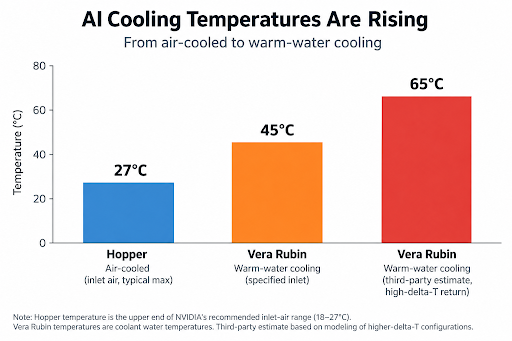
nVidia unveiled this shift at CES in January 2026, announcing that its upcoming Vera Rubin platform would run on 45°C warm water with “no water chillers necessary.” NVIDIA’s reference design describes coolant entering a fully liquid-cooled Vera Rubin rack at up to 45°C (113°F) and exiting at roughly 55°C in typical operation, though third-party modeling has projected return temperatures approaching 65°C in higher-delta-T configurations. Either way, it’s a substantially hotter loop than the chilled-water systems most piping standards were written around.
What changed between Blackwell and Vera Rubin
nVidia’s Blackwell generation (GB200, launched 2024, and GB300, which followed in 2025) already pushed data centers toward direct-to-chip liquid cooling, but ran hybrid — roughly 85% liquid, 15% air. Vera Rubin, entering mass production and shipping in autumn 2026 with cloud partners targeting deployment in the second half of the year, is 100% liquid-cooled: no fans, no air-cooling fallback.
The shift to Vera Rubin compounds several variables at once:
Cooling temperature → flow → pipe size → operating pressure → thermal movement → pressure thrust → nozzle load.
- Higher temperature drives more thermal expansion in every pipe run.
- Higher flow — reported to roughly double per rack versus GB300 — means more velocity, more turbulence, and more pump-driven vibration.
- Larger pipe diameter, needed to carry that flow (row-level distribution has been reported at up to 12 inches, moving around 1,000 gallons per minute), adds thermal mass and force at every fitting.
- Higher operating pressure, common in denser, higher-flow secondary loops, generates pressure thrust. Pressure thrust is the unbalanced axial force an expansion joint exerts on its anchors and adjacent equipment when it isn’t restrained by tie rods.
- All of it converges as nozzle load at the equipment connection — more connections, more piping, attached to more sensitive IT cooling hardware than ever before.
Individually, each of these is manageable. Converging simultaneously, across hundreds of rack-level cooling units per hall, they’re a new engineering problem.
The nozzle load problem… that nobody wants to own
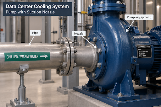
Mechanical equipment can only tolerate limited force and moment at its connections — the “nozzle load.” Exceed it, and you risk cracked welds, misalignment, or seal failure. In high-density liquid cooling, equipment vendors frequently don’t publish allowable nozzle loads at all. New, proprietary hardware on an annual refresh cadence leaves little time for vendors to characterize structural allowables, so engineers must design connections to equipment with effectively unknown tolerances.
When the information around how much load a nozzle can take is limited, not readily available, or simply 0 because that is safe and takes no effort for the mechanical equipment vendor, the responsible and possibly move is to minimize the nozzle load. And to account for pressure thrust separately from thermal movement, since an unanchored or unrestrained expansion joint can push just as hard on a nozzle as thermal growth does.
Why flexible connections are the answer
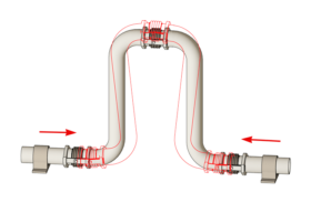
Expansion joints and flex hoses allow the piping to move without putting that stress on the equipment. They absorb thermal expansion, misalignment, and vibration.
That becomes especially important in a Vera Rubin-scale data center, where hundreds of cooling connections may share the same piping system. Without flexibility, movement in the piping can transfer stress to pumps, cooling equipment, and other connections.
Flexible connections let the pipe move while protecting the equipment. Proper anchors and restraints handle the resulting pressure forces.
It’s not just the rack – the whole plant needs to move too
This isn’t only a rack-level issue. The warm-water loop runs through the entire facility plant, and every component has its own nozzles and vibration signature.
- Computer room air-handling units (CRAH). Even with direct liquid cooling (DLC), air cooling is still needed to remove heat from the room and control humidity. Water piping connects to cooling coils inside these units.
- Coolant Distribution Units (CDU). These are the heart of the liquid-cooling system. They circulate coolant to the server racks and transfer heat between the rack cooling loop and the facility water system. Their pumps and heat exchangers need to be protected from piping movement and vibration.
- Air Handling Units (AHUs). Larger air handlers elsewhere in the facility also have water connections that can be affected by pipe movement.
The common problem is simple: the pipes move, but the equipment shouldn’t have to. As cooling systems get hotter and move more water, controlling that movement becomes more important—not just at the server racks, but throughout the cooling system.
Selecting expansion joints when vendor data is undefined
- Design to actual movement and pressure. Calculate thermal growth for the specific run length and realistic supply/return swing, and calculate pressure thrust separately — don’t assume legacy chilled-water tables still apply.
- Size for flow and velocity, not just diameter. Larger, higher-flow lines generate more turbulence-induced vibration; rate connectors for actual velocity and pressure class.
- Treat undefined tolerance as zero tolerance. Without published allowables, design the flexible connection—and its anchoring—to absorb essentially all anticipated movement, vibration, and pressure thrust, rather than splitting the difference with rigid pipe. Good Practice is to allow none of the piping loads to be transferred to the equipment. Keep it at zero load.
- Confirm material compatibility. Warm-water DLC loops often run treated water/glycol at elevated temperatures — match elastomer and liner materials to the actual chemistry, temperature, and pressure range.
- Plan for serviceability at scale. With hundreds of identical connections, field-replaceable bolted or flanged connectors reduce both installation risk and future downtime.
- Document the design basis. Where vendors won’t provide nozzle data, document the calculated assumptions used. It won’t create a number that doesn’t exist, but it creates a defensible engineering record.
What this means going forward
Vera Rubin and the generations that follow will push data center cooling systems to higher temperatures, higher flows, and larger pipes. Data center piping is moving into territory once reserved for industrial process plants.
As liquid cooling expands, managing pipe movement and vibration becomes more important. Expansion joints and flex hoses help protect expensive cooling equipment by keeping those forces from reaching the equipment connections.
This matters throughout the cooling system — from the server rack to the cooling plant.
Have questions about expansion joint selection for a specific liquid cooling deployment? Our engineering team can help review piping layouts, movement and pressure thrust calculations, and material compatibility for high-density data center projects.
Upcoming Live Webinar
Sign-up for a Live Technical Webinar…
U.S. Bellows 101 - The Basics of Expansion Joints
Date: Thursday, October 1, 2026 - Register for 10:00 am OR 2:00 pm
*Note: Time Zone is CDT * Central Daylight Savings Time / GMT -5h
Live Webinars are 1 PE/PDH Credit for TX Professional Engineers
Listen to in-depth explanations on how to choose the type of expansion joint that will best suit your system. Learn about the bellows movements throughout the piping system due to thermal changes of mechanical motion. Increase your understanding of the different types of expansion joints and value-added services offered by U.S. Bellows.
Upcoming Webinars:
September 24th: Pipe Support Engineering & Design Webinar 10:00 am OR 2:00 pm
October 8th: Pipe Clamp Design, Application & Installation Webinar 10:00 am OR 2:00 pm
October 15th: U.S. Bellows - Expansion Joints In-depth Webinar 10:00 am OR 2:00 pm
View video recordings from past webinars…
Online Course
Expansion Joint Application and Design
Our Expansion Joint course was developed for the following disciplines…
- Piping system designers that may decide to use expansion joints
- Expansion joint designers use the information provided by piping system designers to determine the best design to meet the requirements.
- Designers that use modern software systems to evaluate different options
- Engineers / Managers: field, maintenance, process, operations, construction, surveyors
*This online course is approved for 8 hrs. P.E. Credits
Register Now