US Bellows is a Standards Subscriber | Exp: Dec 31, 2026 | See ejma.org to check verification process Celebrating over 20 years of EJMA membership
Resources
Resources
4″ Dia. Single Expansion Joint Designed for a Chemical Facility
Type:
Single Expansion Joint with Control rods
Size:
4″ pipe
Material:
304 Stainless Steel | Carbon Steel
Design
150 PSIG at 300°F spring rate of 425 lb./in
Testing:
100% Dye-penetrant | Hydro-tested
U.S. Bellows Designed and fabricated single expansion joints for a chemical processing facility in Canada. Designed for 4-inch piping, each expansion joint accommodates 1 inch of axial movement with a spring rate of 425 lb./in. The units come with covers to protect the bellows during installation and operation. The units also have control rods to prevent any excess movement from the expansion joint and are designed to contain the pressure thrust in case of an anchor failure. The expansion joints are rated for a design pressure of 150 PSIG at 300°F, ensuring reliable performance under demanding operating conditions.
To verify quality and performance, each expansion joint underwent 100% dye penetrant examination and a hydrostatic pressure test prior to shipment, ensuring compliance with the project’s stringent quality requirements and providing the customer with a dependable, high-quality solution.
Oversized vs Same-Size Clamshell: Choosing the Right Repair for Your Piping System
When a metallic bellows fails, the priority is restoring system integrity with minimal disruption to operations. In many facilities, the standard approach of removing and replacing the existing expansion joint is not always practical. Surrounding piping, structural steel, refractory systems, or insulation can make removal time-consuming, costly, and in some cases, simply not feasible within the available outage window.
A clamshell bellows addresses this directly. US Bellows fabricates two distinct configurations: oversized and the same size clamshells. Selecting the right one depends on the specific conditions of the repair.
This article explains how each type works, when to use one over the other, and what to consider before contacting an engineer.
What Is a Clamshell Bellows?
A clamshell bellows is a split metallic bellows assembly manufactured in two longitudinal halves. The halves are assembled around the damaged or leaking bellows and welded together, either in the field or in the shop, without requiring the full removal of adjacent piping, structural components, or surrounding equipment.
Clamshell bellows are fabricated in single-ply metallic bellows only. They are not suitable for fabric or rubber expansion joints, in these cases, contact us to discuss repair options. There are no inherent pressure or temperature class restrictions; each assembly is custom-designed to the material, geometry, and service conditions of the existing joint.
Note – Clamshell bellows are a temporary repair solution. They restore system containment and allow continued operation while a permanent replacement is planned.
Oversized Clamshell Model
Same-Size Clamshell
The Two Configurations
Oversized Clamshell
An oversized clamshell uses rings to increase the enclosure diameter beyond that of the existing bellows. The assembly is built to enclose the failed joint from the outside, without making contact with it, cutting it, or removing it. The repair is performed entirely in the field.
This configuration is used when removing the existing bellows is not practical. Large-diameter joints surrounded by permanent piping, structural steel, refractory, or insulation are typical candidates. In these situations, the cost and time required to dismantle the surrounding system can far exceed the cost of the clamshell itself. The oversized design eliminates that work entirely.
Field installation requires slow, precise welding along the longitudinal seams. Access constraints, working at elevation, and tight clearances all add to the complexity of the weld. This is the primary tradeoff of the oversized configuration: it avoids disassembly, but the field weld must be executed carefully under site conditions.
Same-Size Clamshell
A same-size clamshell is manufactured to match the dimensions of the existing bellows. It is designed for situations where the existing joint, or the equipment it is part of, can be removed and either sent to the US Bellows facility for a shop repair or replaced in the field after the original bellows has been taken out.
This configuration is better suited for turnaround scenarios. When a failed bellows is discovered during a planned or unplanned outage, and there is sufficient time to remove the joint, a same-size clamshell can be fabricated and installed with tighter quality control, full weld access, and US Bellows can provide complete ASME documentation when required.
Comparison at a Glance
Oversized Clamshell
Same-Size Clamshell
How it works
Rings increase the enclosure diameter to fit over the existing bellows
Manufactured to match the dimensions of the existing bellows
Best suited for
Large-diameter field repairs, emergencies where removing the existing joint is impractical
Turnarounds where the equipment can be sent to the shop or the EJ can be removed in the field
Installation
Field-welded in place around the existing failed joint
Shop repair at the US Bellows facility, or field installation after joint removal
Key advantage
No need to cut, remove, or disturb the existing bellows or surrounding components
Tighter quality control, full weld access, and ASME documentation are more straightforward
Primary tradeoff
Higher fabrication cost; field welding required under site conditions
Removal of the existing joint or equipment adds time and labor
Typical application
Large-diameter lines with surrounding refractory, structural steel, or insulation
Heat exchangers, turnaround repairs with a sufficient outage window
How to Determine Which Configuration Fits Your Situation
The decision comes down to two questions:
1. Can the existing bellows or equipment be removed?
If yes, and there is time in the outage window to do it, the preferred option is for a new bellows replacement to be provided. However, in cases such as heat exchangers, where disassembly would be time-consuming, a same-size clamshell is generally the more controlled repair. It allows for shop fabrication, easier welding, and straightforward ASME documentation.
If removal would require cutting permanent piping, dismantling structural supports, removing refractory or insulation, or using crane support for a large-diameter joint, an oversized clamshell avoids that work entirely.
2. What are the access conditions at the joint location?
Oversized clamshells are designed specifically for constrained conditions. If the joint is surrounded by equipment, located at elevation, or embedded in a system where adjacent components cannot easily be disturbed, field installation of an oversized clamshell is the practical path.
What US Bellows Needs to Design A Clampshell
Regardless of which configuration applies, the following information is required to start the engineering review:
Nominal pipe size and bellows outside diameter
Material and ply count of the existing bellows
Design pressure and temperature
Type of movement accommodated (axial, lateral, angular)
Accessibility constraints and site conditions
Drawings or dimensional sketches of the existing assembly, when available
For urgent repairs, US Bellows’ engineering team is available around the clock. Both configurations can be designed and fabricated on emergency turnaround schedules when the situation requires it.
Elbow Pressure Balanced Expansion Joint Designed for a Chemical Processing Plant
US Bellows custom-designed and manufactured an 18-inch diameter elbow pressure balanced expansion joint for a chemical processing plant used in the production of compound fertilizers. The expansion joint was engineered to accommodate thermal movement while minimizing pressure thrust loads in the piping system, making it well suited for the plant’s nitrogen oxide process.
The assembly measured 83-3/8 inches from the weld end to the centerline of the elbow. The body, pipe, covers, and tie rods were fabricated from 304L stainless steel, while the bellows and internal liners were manufactured from 321 stainless steel for enhanced high-temperature performance. The unit was designed to accommodate 1/2 inch of axial compression and 4-1/8 inches of lateral movement while operating at 600°F and 125 psig.
As part of PT&P’s quality assurance program, the completed assembly underwent 100% dye-penetrant examination and a hydrostatic pressure test at 190 psig prior to shipment to verify structural integrity and compliance with project specifications
Fabric Expansion Joint Custom Designed for an Exhaust Application in a Gas Turbine Facility
US Bellows custom-designed and manufactured this 153″ x 55″ x 21″ fabric expansion joint for an exhaust application at a gas turbine facility overseas. The expansion joint features a carbon steel frame and liner with a protective painted finish. The flexible element consists of a reinforced neoprene fabric belt designed to accommodate system movement while maintaining reliable performance under demanding operating conditions.
The assembly was engineered for a pressure rating of ±100″ water column and operating temperatures ranging from -20°F to 600°F. Prior to shipment, the expansion joint underwent a 100% dye-penetrant examination and paint thickness inspection to verify compliance with project quality requirements.
US Bellows specializes in the design and manufacture of custom fabric expansion joints for gas turbine exhaust systems, power generation facilities, industrial ducting, and other applications requiring flexibility, vibration isolation, and thermal expansion compensation.
What Information Manufacturers Need to Design an Expansion Joint
The quality of an expansion joint is determined long before fabrication begins. It is determined by the accuracy and completeness of the information a customer provides at the specification stage. Incomplete data forces assumptions, and these assumptions often lead to joints that fail early, require rework, or arrive dimensionally incompatible with the system for which they were built.
US Bellows works across metal, rubber, and fabric expansion joints for refineries, power plants, chemical facilities, LNG plants, and data centers. The specification process is the same regardless of application, every successful design begins with the same core inputs.
What the System Carries Determines What the Joint Must Be
Pressure and temperature are the two parameters that determine the material selection of the expansion joint. The table below outlines the operational limits and typical applications for each joint type.
Joint Type
Max Temperature
Pressure Range
Typical Applications
Fabric
1,500°F+
±3 PSI
Exhaust ducting, HVAC, low-pressure gas
Rubber
300–350°F
Moderate, Up to 300 PSI (smaller diameters)
Water treatment, pump discharge lines
Metal
2,000°F+ (depending on insulation)
Highest rated
Refineries, chemical plants, steam systems
Equally important is the media, what is flowing through the pipe. Corrosive fluids, acids, and certain gases may be incompatible with rubber, fabric, and standard stainless steel alloys. Specifying the wrong material for the media leads to chemical degradation before the joint reaches its rated service life. For hazardous gas applications, hydrogen fluoride, carbon monoxide, or acid gas, additional design codes and testing requirements apply that cannot be accommodated after the fact. Customers must disclose the media at the point of inquiry.
The Dimensions and Connection Details
Manufacturers need the pipe diameter, wall thickness, schedule, and end connection type. End connections come in many forms (i.e, threaded connections, couplings) but the two main ones are:
Welded pipe ends — the joint is welded directly into the pipe run and cannot be removed without cutting
Flanged ends — bolted connections that allow the joint to be unbolted and removed for maintenance access
Overall length is equally critical. In replacement applications, the face-to-face dimension is fixed by the existing installation and must be measured from the line, not from a drawing. In new installations, the available space between anchors, turbines, elbows, and nozzles defines the physical envelope the joint must fit within.
How the Pipe Moves and the Force Required to Drive It
Metal Expansion joints absorb three types of movement, each of which affects joint selection:
Axial — compression and extension along the pipe axis; handled by a single joint in any material
Lateral — transverse displacement; fabric and rubber accommodate this within a single unit, metal requires a universal or double configuration.
Angular — rotation about a fixed point; typically ±10° for metal, up to 30° for fabric and rubber
Torsional – Metal Expansion joints are not recommended for Torsional Motion. Rubber and fabric can handle this motion.
Customers must also state the expected number of thermal cycles. A joint designed for 1,000 cycles that is cycling daily will reach its fatigue limit within three years. For engineers running pipe stress analysis, the spring rate, the force required to compress the bellows by one inch, is an essential output that feeds directly into the piping model.
Another equally important detail for Pipe stress analysis and expansion joint is, whether the expansion joint will contain the pressure thrust of the line. This can be done via tie-rods, hinges, gimbal or a Pressure balanced EJ. If you are unfamiliar with this, contact us and we can discuss the options for your Piping design.
The Parameter Most Customers Under-Specify and What It Costs
Flow velocity is among the most frequently omitted parameters in expansion joint specifications, and consistently the most damaging when wrong.
US Bellows was engaged by an LNG plant experiencing repeated internal liner failures under bi-directional flow. Robotic inspection and X-ray analysis revealed widespread buckling throughout the metallic bellows installation. FEA and computational fluid dynamics identified the cause: liquid nitrogen running at 65 feet per second, far beyond the liner’s yield threshold. US Bellows recommended capping velocity at 10 feet per second and fabricated replacement bellows to that specification.
Less visible is turbulence caused by nearby equipment. A butterfly valve positioned immediately upstream of a bellows disrupts flow sufficiently to induce vibration even at low velocity. Customers should disclose all valves, fittings, and equipment in proximity to the intended bellows location.
The Code That Governs the Design Also Determines the Testing
The applicable piping design standard should be stated at the inquiry stage:
ASME B31.1 — power piping; references EJMA as the governing document for bellows design
ASME B31.3 — process piping for oil, gas, and chemical facilities; includes Category M criteria for critical and hazardous service
ASME Section 8 Division 1 — pressure vessel applications; uses a distinct set of design equations independent of EJMA
The applicable code determines whether X-ray, ultrasonic, or additional NDE testing is required. Customers who specify the applicable code from the outset avoid discovering mandatory testing requirements after fabrication has begun.
For critical installations where bellows failure would force a plant shutdown, US Bellows recommends two precautions: ordering a spare joint to minimise replacement downtime, and specifying two-ply testable bellows with a test port that detects inner ply failure before a complete breakdown occurs.
What Ships With Every Expansion Joint
Every expansion joint undergoes a leak test before dispatch. Every expansion joint that we fabricate will have at minimum the following records:
Material Traceability Record (MTR) for pressure retaining parts
Certificate of Conformance(COC)
Non-destructive examination (NDE) reports
Leak or pressure test report
Customers requiring review of quality documentation before shipment should state this at the order stage. All products carry a warranty of one year after installation or 18 months after shipment, whichever occurs first, provided the joint is installed and operated as intended.
Complete specifications at inquiry don’t just start the process right, they keep it right, from first design to final performance
20″ Dia. Double Gimbal Expansion Joint Refurbished for an Oil Refinery
US Bellows successfully refurbished this double gimbal expansion joint for an oil refinery located in Baton Rouge, Louisiana, extending the service life of the existing equipment while restoring its performance and reliability. The expansion joint is being used on a tank to accommodate the differential settlement due to the immense weight of the tank and the piping connected to it. This refurbishment was completed in less than two weeks.
As part of the refurbishment, the overall length was modified due to settlement variations, and the original bellows were replaced with new bellows fabricated from Inconel® 625, a high-performance nickel-based alloy known for its exceptional resistance to corrosion, oxidation, and elevated-temperature service. The flanges, pipe and bellows reinforcements made of Carbon steel were replaced after inspection due to the corrosion and the criticality of the components, while the hardware components (gimbal box and supports) were all repaired and refurbished..
The expansion joint measures 20 inches in diameter with an overall length of 108 inches. It was designed to accommodate 4 inches of lateral movement while operating at temperatures up to 450°F and pressures of 180 psig.
To ensure compliance with the refinery’s quality requirements, U.S. Bellows performed a comprehensive inspection and testing program prior to shipment. The refurbished unit underwent 100% dye penetrant examination, Positive Material Identification (PMI) testing, and a hydrostatic pressure test to verify material integrity, weld quality, and overall performance.
This project highlights U.S. Bellows’ expertise in both the manufacture of new expansion joints and the refurbishment of existing units, providing customers with cost-effective solutions that improve reliability and extend equipment service life in demanding refinery applications.
25 Years of Proven Performance — US Bellows Delivers Again
When a major energy provider needed to replace a critical elbow pressure balanced expansion joint at one of its Nevada power generation facilities, it turned to a trusted manufacturer.
US Bellows re-engineered and refurbished this elbow-pressure balanced expansion joint, which had lasted more than 25 years. The original unit, manufactured in 1975, is for a GE steam turbine used in the cross-over pipe section to manage thermal expansion while minimizing loads on the turbine. US Bellows refurbished and replaced the bellows 25 years ago. After the bellows has a full-service life the client turned to us for another replacement—and we turned it around in three weeks.
The Challenge The expansion joint required custom fabrication to exact specifications, with a three-week deadline to minimize downtime at an active gas-fired power plant.
The US Bellows Difference Expansion joints are a technically demanding, artisanal product line requiring rare skills, thin-gauge superalloy welding, and custom machinery. Here’s what made it possible:
Scale & Capacity: US Bellows shipped nearly 4,500 expansion joints last year, backed by a 15% shop expansion and new equipment including a CNC plasma table, bellows shear, Davi roller, additional in-house designed punch equipment, clean-room operations, and additional cranes.
Workforce Flexibility: Our expansion joint team can draw on 40+ additional trained welders and 30+ cut shop and layout personnel when needed — ensuring we can surge capacity to meet urgent deadlines. Our ability to be vertically integrated with our other divisions from a manufacturing standpoint gives us the optimal set up for fastest time to market in these scenarios.
Engineering Expertise: Two dedicated industrial engineers with master’s degrees drive on-floor scheduling and process efficiency, with the entire production process mapped for rapid response.
Digital Work Instructions: Deployed across all key production steps, enabling precision, consistency, and fast execution — even on complex custom fabrications.
Enhanced Quality Control: Detailed drawing review checklists before fabrication reduce revisions and reworks, so we get it right the first time.
As an EJMA-certified manufacturer, all of our expansion joints are designed and fabricated in accordance with EJMA standards and ASME B31.1 Power Piping Code for power applications — ensuring every unit meets the rigorous demands of power generation environments.
Why the Elbow Pressure Balanced Expansion Joint Matters
In today’s power landscape — driven by AI data centers, industrial electrification, and aging grids — turbines must operate with near-zero downtime. Even a few millimeters of unintended movement from thermal expansion in steam lines can cause casing distortion, rotor misalignment, and bearing failure.
The Elbow Pressure Balanced Expansion Joint (EPBEJ) is engineered to prevent exactly that — while solving a challenge the inline design cannot: changes in piping direction.
Force Neutralization at the Elbow: A balancing bellows positioned after the elbow cancels out pressure thrust in both the axial and lateral directions via tie rods — so the turbine flange experiences zero pressure-related loads, even through a 90° turn.
Zero-Anchor Load: The turbine only “feels” the minimal spring rate of the bellows — negligible compared to the thousands of pounds of thrust generated by pressure acting on directional changes in high-pressure steam lines.
Direction Change Without Penalty: The elbow design absorbs thermal growth across a piping bend, eliminating the need for separate directional expansion joints or complex guided pipe loops at header-to-turbine connections.
Reduced Civil Costs: The self-balancing design eliminates the need for massive concrete thrust anchors at elbow locations — historically among the most heavily loaded anchor points in a turbine hall.
Compact Routing in Tight Layouts: Where piping must turn to reach a turbine nozzle, the EPBEJ replaces what would otherwise require multiple components — an elbow, two expansion joints, and intermediate anchoring — with a single, integrated assembly.
Reliability in Cycling: As peaking plants ramp up and down daily to balance renewables, the EPBEJ absorbs constant expansion and contraction cycles at directional transitions that would otherwise fatigue turbine nozzle connections and elbow welds alike.
A Legacy of Quality The original elbow pressure balanced expansion joint served this client for 50+ years. When the time came for a replacement, they came back to us. That’s the US Bellows standard — products built to last, and a team built to deliver.
60% of our work at US Bellows is replacement units for operating facilities all over the world. We are not always the OEM — but we are always the manufacturer that delivers.
At US Bellows, we build lasting partnerships with the power industry — one precision-engineered solution at a time.
5 Questions to Ask Before Ordering a Replacement Expansion Joint
Expansion joints are engineered solutions, not off-the-shelf components. When one fails, replacing it like-for-like without evaluating system conditions, operating history, and installation constraints is the fastest way to repeat the failure.
The following questions provide a practical framework for ensuring the correct selection.
Question 1: Do You Have the Original Design Specifications or Drawings?
The most reliable way to specify a replacement expansion joint is by referencing original design documentation, including drawings, datasheets, or nameplate data. While pressure and design temperature are the primary controlling factors, a complete specification requires the full STAMPED criteria: Size, Temperature, Application, Movement, Materials, Pressure, Ends, and Delivery. Missing any of these can lead to delays or incorrect selection.
Material selection follows directly from these numbers:
JointType
Temperature Limit
Pressure Range
Typical Applications
Fabric
Upto 2000°F
Low (+/-3psi)
Exhaust ducting, HVAC, low-pressure gas
Rubber
Upto 350°F
Medium
Water treatment, pump discharge lines
Metal – Stainless Steel
Upto 1200°F
High
Refineries, chemical plants, steam lines
Metal – Nickel Alloy
Up to 2800°F
Extreme
Steel plants, acid plants, aerospace
Question 2: How Long Did the Previous Joint Last, and What Was the Failure Mode?
Service life is one of the most diagnostic data points available when specifying a replacement. It tells you if the original product selection was correct, or whether there is a systemic issue that a new joint will not solve.
Joint lasted 15–20 years: The original specification was appropriate. Failure is the result of normal fatigue or corrosion. A like-for-like replacement is the correct approach.
Joint failed in under 12 months: There is an underlying cause that replacement alone will not fix.
Understanding the Failure Mode
The most frequent cause of premature failure in metal bellows is piping misalignment. Expansion joints are designed to accommodate minor axial, lateral, and angular misalignment, but that tolerance is not a substitute for correct pipe alignment.
Physical handling damage is the second most common cause. Bellows are manufactured from thin-wall metal (typically 0.015″ to 0.065″ wall thickness). A dent or crease before the joint enters service creates a stress riser that accelerates failure.
Question 3: Were There Any Upset Events During or Near the Joint’s Failure?
Design conditions represent normal operation, but failures often occur during transient or abnormal events, especially those occurring shortly before or at the time of failure.
Before placing your order, check whether any of the following occurred:
Overpressurisation – A pressure spike above MAWP can cause the bellows convolutions to balloon permanently outward, a condition known as squirm.
Water hammer – Rapid valve closure or pump startup creates pressure transients that can shock-load the bellows.
Flow-induced vibration – High-velocity flow or proximity to rotating equipment, pumps, compressors, turbines, cycles the bellows at frequencies that rapidly consume fatigue life.
Flag any upset events when placing your order. The engineering team may recommend design modifications based on the actual service history.
Question 4: Are the Existing Dimensions Accurate to the Original Design?
Incorrect dimensional assumptions are a common cause of replacement failures. A key mistake is assuming that the installed joint dimensions reflect the original design intent. In many cases, they do not.
Before ordering, verify the following:
Face-to-face (F-F) dimension between mating flanges
Pipe outside diameter (OD)
Flange bolt-circle diameter (BCD) and bolt-hole pattern
Tie rod length and stop nut positions
Critical Check – Confirm whether the current dimensions match the original drawings, or if they reflect field modifications. Designing to incorrect field dimensions can introduce unintended stresses into the new joint.
Question 5: Is the Original Material Selection Still Appropriate for the Current Service?
Operating conditions change over a system’s life. A joint specified for moderate-temperature steam service may now be running a corrosive fluid at elevated pressure.
Corrosive environments- Standard 304 or 316 stainless steel performs well in neutral applications. In high-chloride, acid, or caustic service, these alloys are susceptible to stress corrosion cracking. Specialty nickel alloys such as Inconel 625 or Hastelloy C-276 are frequently required.
Vibration-sensitive applications- Rubber joints provide effective isolation in pump discharge and water service lines. Metal joints with internal flow liners are preferred for high-velocity gas applications.
Changed pressure or temperature ratings- If the line now operates beyond the original design envelope, a direct replacement is a code compliance issue.
Address the Root Cause & Strengthen Your Piping System with US Bellows
The most expensive maintenance pattern US Bellows engineers encounter is repeated bellows replacement without addressing the root cause of failure in the piping support system.
If original specifications or documentation are unavailable, the existing expansion joint can be sent for detailed examination. This enables accurate measurements and reverse engineering, allowing the engineering team to recommend the most appropriate solution.
In many cases, the root cause lies beyond the joint itself, in system alignment, supports, or operating conditions. US Bellows’ in-house field service team inspects complete piping systems to identify these issues and deliver long-term solutions. Schedule a consultation with a US Bellows engineer or request a quote with your specifications.
153″ Fabric Neoprene Expansion Joint for an Air Re-circulation/Ventilation Application at a Gas Turbine Facility in Hungary
Type:
Neoprene Expansion Joint
Size:
153″ x 55″ x 21″
Design:
EPDM Reinforced Fabric Cloth | A572 Grade 50
Material:
200°F, +/- 100″ WC, & 1″ Axial
Testing:
Dye-penetrant examination
For this project, U.S. Bellows designed and manufactured a customEPDM neoprene expansion jointfor an air recirculation and ventilation application at a gas turbine facility in Hungary.
The unit measures 153″ long x 55″ wide x 21″ face-to-face and was engineered to absorb movement and vibration within the ventilation system while maintaining reliable operation under demanding service conditions.
Designed for operating temperatures up to 200°F and pressures of ±100 inches water column, the expansion joint accommodates 1 inch of axial compression and lateral deflection to support thermal movement and system flexibility.
The flexible fabric belt was constructed from neoprene-reinforced fabric cloth, selected for its durability and resistance to heat and environmental exposure. The supporting framework was fabricated from A572 Grade 50 carbon steel to provide the structural integrity required for the application and coated after welding.
Due to US Bellows’ engineering expertise and proven performance in critical power generation applications, the customer selected U.S. Bellows as the sole-source supplier for this expansion joint scope.
This project also reflects the long-term confidence customers place in US Bellows. Our team has worked strategically with this client for more than a decade, supporting evolving expansion joint requirements across critical applications and international projects.
This project highlights U.S. Bellows’ continued commitment to delivering custom-engineered fabric expansion joint solutions for demanding power-generation and industrial-ventilation applications worldwide.
Case Study: Delivering 200+ Expansion Joints in Record Time for a Large-Scale Battery Manufacturing Facility
As global demand for battery production continues to accelerate, a major manufacturing facility undertook the development of a large-scale plant spanning two production buildings, requiring a highly coordinated piping infrastructure across multiple utility systems. These systems included chilled water, steam, nitrogen, compressed air, and condensate, all of which demanded precise engineering to ensure long-term reliability.
Due to the facility’s scale and complexity, piping systems needed to accommodate thermal expansion, lateral movement, and seismic activity, all within limited space and under an aggressive construction timeline. To meet these demands, Piping Technology & Products and its subsidiary, US Bellows, were selected to provide a fully integrated expansion joint and pipe support solution.
The Challenge
Initial piping designs relied on traditional solutions such as pipe loops and flexible hose assemblies. However, these approaches introduced significant limitations:
Limited Space Availability Large pipe loops were impractical in congested mechanical corridors and overhead routing areas, restricting design flexibility.
Complex Movement Requirements The system needed to absorb multi-directional movement—including axial, lateral, and seismic displacement—without compromising performance.
Fragmented Procurement Strategy Using multiple vendors for expansion joints, supports, and analysis increased coordination challenges and project risk.
Aggressive Schedule Constraints Long lead times and decentralized sourcing threatened to delay construction and impact overall project delivery.
The project required a more compact, efficient, and fully engineered solution that could address movement requirements while simplifying both procurement and installation.
The Engineered Solution
To overcome these challenges, US Bellows developed a custom nested Super U-Loop configuration using metallic expansion joints, replacing traditional pipe loop designs.
As illustrated in the engineering layout diagram on page 2, the nested configuration allows multiple expansion joints to work together within a compact footprint, effectively absorbing movement without requiring large spatial allowances.
This approach provided several advantages:
Efficient absorption of thermal and lateral movement within constrained spaces
Improved system reliability compared to flexible hose designs
Reduced footprint, enabling installation in tight routing environments
Integrated Engineering Approach
Piping Technology delivered a single-source solution, combining multiple components into one coordinated system:
Metallic expansion joints
Pipe expansion U-loops
Engineered pipe supports
Guides and anchors
Comprehensive pipe stress analysis
This integrated model significantly reduced interface risk while improving design coordination and execution efficiency.
Close collaboration between engineering teams, contractors, and field personnel ensured that all designs aligned with real-world installation conditions, minimizing delays and rework.
Advanced Engineering & Design Features
The solution was supported by detailed pipe stress analysis, validating performance under thermal, pressure, and seismic loading conditions. Key design elements included:
Nested expansion joint configuration for multi-directional movement
Flow liners to protect against turbulence and internal wear
Protective covers to enhance durability and extend service life
Custom supports and guides to control movement and maintain system integrity
PE-stamped calculations and drawings for full engineering validation
This level of engineering ensured both fit within tight layouts and reliable long-term performance across all operating conditions.
Field Support & Responsiveness
Following installation, minor field constraints were identified that limited the movement of certain expansion joints.
US Bellows and Piping Technology responded rapidly by:
Evaluating on-site conditions
Providing updated engineering recommendations
Supporting field adjustments to restore proper functionality
This proactive response minimized operational disruption and ensured the system performed as intended without major rework.
Results
The project demonstrated the combined strength of engineering expertise and manufacturing capability:
Engineered Performance
Successfully accommodated thermal, lateral, and seismic movement
Eliminated the need for large, space-consuming pipe loops
Delivered a more reliable and maintainable piping solution
Manufacturing & Execution
Supplied 200+ expansion joints ranging from 4” to 36”
Delivered over 400 product configurations and 6,000+ total units
Completed 69 coordinated shipments to match construction sequencing
Executed the entire scope within approximately five months
Project Value
Simplified procurement through a single-source solution
Improved installation efficiency and reduced field modifications
Supported aggressive construction timelines with responsive delivery
Conclusion
By replacing traditional pipe loop designs with a compact, engineered Super U-Loop expansion joint solution, Piping Technology & Products and US Bellows delivered a high-performance system tailored to the demands of modern battery manufacturing facilities.
The project highlights the value of integrated engineering, innovative design, and responsive execution, enabling complex industrial projects to meet tight schedules without compromising reliability or performance.
Gimbal Expansion Joints for Crude Oil Pipelines in Canada
U.S. Bellows custom-designed and fabricated 24-inch universal gimbal expansion joints for crude oil pipelines at a power plant in Canada, delivering a robust solution for managing angular movement and system stress.
The bellows were manufactured from ASTM A240 Type 316 stainless steel, providing excellent corrosion resistance and durability. The flanges were fabricated from A105 carbon steel, and the gimbal assemblies were constructed from A516 Grade 70 carbon steel, ensuring structural strength and reliability under demanding operating conditions.
These expansion joints were engineered to accommodate 10° of angular rotation at 285 psig and temperatures up to 100°F. The design includes an angular spring rate of 4,900 in-lb/degree and allows for a vertical offset of 10-1/4 inches, supporting system flexibility while maintaining load control. The overall dimensions of the units are 43″ x 43″ x 110″ and 38″ x 38″ x 79″.
Advanced 3D modeling was utilized during the design phase to verify proper fit-up within the system, perform Finite Element Analysis (FEA) on critical components, and provide the customer with detailed models for integration into their plant design prior to fabrication.
To ensure quality and compliance, each unit underwent hydrostatic testing, non-destructive examination (NDE), and was delivered with complete Material Test Reports (MTRs) in accordance with the client’s specifications.
This project highlights U.S. Bellows’ capability to deliver high-performance, custom-engineered expansion joints supported by advanced analysis, rigorous testing, and value-added engineering services.
66″ Diameter Hinged Expansion Joints Designed for a Chemical Plant
Type:
Hinged Expansion Joint
Size:
66″ in diameter and 39-3/8″ OAL
Material:
Incoloy 825 / 321 stainless steel
Design
73 PSIG at 986°F with 4.25 degrees of angular rotation
Testing:
Dye Penetrant, X-Ray, PMI, Hydrotest
These single hinged expansion joints were custom designed by US Bellows for a chemical plant in Saudi Arabia to manage the critical piping systems. The units are 66″ in diameter and 39-3/8″ OAL. The bellows were fabricated from Incoloy 825 with the weld ends, hinges, liner, and cover from 321 stainless steel. The expansion joints were designed for an operating pressure of 73 PSIG at 986°F with 4.25 degrees of angular rotation. All units were dye-penetrant tested and x-ray tested on each bellows and pipe longitudinal weld seams, PMI tested on each alloy component, and ultrasonic tested on each alloy steel plate prior to shipment. Hinged expansion joints contain hinges or pivots which allow the unit to bend in a single plane.
We’ve supplied this type of expansion joint for both methanol and ammonia plants. They are also used in piping systems for air, steam, gas turbines, reformer ducts, and burners. These units are designed to restrict axial deflection in extension or compression. The hinge mechanism is designed to contain full-pressure thrust. Also, because of the hinge mechanism’s design, shear loads, such as from the weight of adjacent piping, can be accepted by this pipe expansion joint, relieving the piping designer of having to provide additional supports and anchors required by the single type.
Product Overview
US Bellows designs and manufactures single hinged expansion joints engineered to absorb angular rotation in critical piping systems. Compliant with EJMA (Expansion Joint Manufacturers Association) standards, these units are built to handle extreme operating conditions — including high temperature, high pressure, and corrosive media — across petrochemical, power generation, and industrial process applications.
Featured Project: Saudi Arabia Chemical Plant
This custom-engineered single hinged expansion joint was manufactured for a chemical plant in Saudi Arabia serving critical piping infrastructure. The units measure 66″ in diameter with a 39-3/8″ overall length. Bellows were fabricated from Incoloy 825, with weld ends, hinges, liner, and cover constructed from 321 stainless steel. The joints were designed for an operating pressure of 73 PSIG at 986°F (530°C), with an angular rotation capacity of 4.25°. Prior to shipment, all units underwent dye-penetrant and radiographic (X-ray) testing on every bellows and pipe longitudinal weld seam, Positive Material Identification (PMI) on each alloy component, and ultrasonic testing on all alloy steel plate — ensuring full traceability and compliance with the project’s quality requirements.
How Single Hinged Expansion Joints Work
Single hinged expansion joints incorporate a hinge and pivot mechanism that permits angular rotation in a single plane while mechanically restraining axial movement in both extension and compression. Unlike unrestrained expansion joint types, the hinge assembly is rated to absorb full pressure thrust loads, eliminating the need for main anchors in many piping configurations. Because the hinge mechanism also accepts shear loads — including the dead weight of adjacent piping — fewer external pipe supports and guides are required, reducing installed system cost and structural complexity. This behavior is consistent with EJMA’s guidance on restrained expansion joint systems. To accommodate full angular rotation, single hinged expansion joints are typically installed in pairs or sets of three with appropriate anchor and guide arrangements, as outlined in EJMA standards.
Applications
US Bellows has supplied single hinged expansion joints for methanol and ammonia plants, steam and gas turbine exhaust systems, reformer and process gas ducting, combustion air and burner systems, and a wide range of high-temperature gas and air piping applications. These units perform reliably where fixed supports cannot manage thermal growth and where the pressure thrust forces must be fully restrained at the joint itself. US Bellows differentiates through full in-house fabrication, custom metallurgy selection, and rigorous third-party testing documentation delivered with every order.
Materials of Construction
Bellows are available in Incoloy 825, 321 SS, 316L SS, Inconel 625, Hastelloy C-276, and other high-performance alloys depending on process chemistry and temperature range. End fittings, liners, and hinge hardware are material-matched to the process environment and fabricated to customer specification, with full PMI verification on all alloy components as standard practice.
Why Choose US Bellows
US Bellows delivers EJMA-compliant design and documentation with full in-house fabrication from raw plate through final assembly. Every unit is custom-engineered for the specific operating conditions of the application — including non-standard diameters, pressures, and temperatures. Comprehensive NDE including dye-penetrant, radiographic, ultrasonic, and PMI testing is standard on all alloy components. US Bellows has a proven global supply record serving methanol, ammonia, refinery, and power generation facilities, and units are available with ASME Code stamping and third-party inspection upon request.
PT&P REF. ORIGINAL POST 06182019
Efficient Thermal Movement Solutions for Airport Piping
Supporting a Large International Airport in Florida’s Modernization of a Concourse Without the Need for Extra Guides
Nested U-loops are vital for piping systems that undergo thermal expansion and contraction over long distances. When traditional expansion joints require too much supplementary infrastructure, our custom-engineered U-loops step in. We accommodate extreme thermal movement while minimizing the need for additional structural supports.
What is a Nested U-Loop?
A nested U-loop is a specialized piping configuration that helps to absorb thermal expansion.
Unlike standard inline expansion joints that often require a complex system of anchors and guides to function properly, nested U-loops manage movement organically. These configurations are essential for:
Managing Extensive Thermal Movement: Absorbing high degrees of expansion and contraction across long straight pipe runs, as well as large lateral movements.
Reducing Structural Requirements: Eliminating the need for additional pipe guides and structural supports by having the expansion joint contain the pressure thrust.
Streamlining Installation: Providing a reliable, low-maintenance solution for tight or constrained installation footprints.
US Bellows, a division of Piping Technology & Products, engineers and manufactures nested U-loops and conducts comprehensive pipe stress analyses to meet exact project needs. If you are routing chilled-water lines or high-temperature steam, we design loops that meet your specific thermal, spatial, and load requirements.
Case Study: Custom Nested U-Loops for Large Florida Airport
For the ongoing modernization of a concourse, US Bellows supplied customized nested U-loops. This large airport is currently expanding to increase capacity and drastically enhance the passenger experience.
The Challenge: During Phase 2 of the project, mechanical contractors were tasked with installing chilled-water piping on the facility’s roof. The design featured 500 feet of straight pipe with no expansion joints and no existing way to manage thermal expansion and movement. Using traditional expansion joints across this massive span would have required the airport to install more guides and supports, increasing costs and installation time.
The Solution: Our engineering team provided the necessary design data for the expansion joints, enabling the contractor to perform a comprehensive pipe stress analysis to calculate and address the exact thermal movement in the chilled water return lines. Our engineering team worked with the contractor to work around their hardware and support spacing to prevent any contact during operation. Based on this analysis, we designed a solution consisting of just four nested U-loops.
The Result: The four nested U-loops effectively addressed all thermal movement across the 500-foot straight pipe run. By avoiding traditional expansion joints, the airport bypassed the need for additional guides and supports.
This critical infrastructure directly supports the concourse’s new amenities, including a dedicated sensory room to provide a calming space for travelers with autism and sensory sensitivities, as well as the infrastructure required for two additional passenger boarding bridges.
Designed for Commercial Infrastructure Demands
In major commercial infrastructure and airport expansions, efficiency and reliability are key. Piping systems face constant environmental variables:
Thermal Expansion: Long pipe runs expand and contract with temperature changes; the system must accommodate these changes.
Space Constraints: Rooftop and utility corridor installations often lack the structural backing for heavy, traditional anchor/guide setups.
Our custom nested U-loops deliver the flexibility contractors need. We minimize installation complexity and protect your facility’s critical systems.
Additional Solutions for Commercial Applications
In addition to nested U-loops and pipe stress analysis, PT&P and US Bellows offer a full range of products for large-scale infrastructure projects:
Standard Expansion Joints: Fabric, metal, and rubber joints to absorb movement and vibration.
Pipe Shoes and Saddles: To support long spans and prevent damage to insulation.
Variable Spring Hangers: For locations requiring vertical travel management.
Pipe Anchors and Guides: To absorb piping loads and direct pipe movement safely.
Each product is made to meet your project’s specific load, movement, and environmental needs.
Why Project Managers Trust US Bellows & Piping Technology
When you work with us, you get a team that solves hard problems. We engineer solutions. We offer:
Comprehensive Engineering: Real-time help from seasoned engineers, including advanced pipe stress analysis.
Custom Design: We build and optimize what competitors deem too complex to handle.
Proven Quality: We meet strict industry standards for safety and performance.
Fast Response: We answer questions, provide feedback, and fix field issues quickly.
For Project Managers, this means less rework, fewer supports to install, and more confidence. Your project stays on track.
Get the Right Solutions for Your Next Project
Talk to a US Bellows engineer today. Discuss your long pipe runs, thermal movement challenges, and tight spaces. We will design a custom solution for you.
Boost Duct System Flexibility with Metal Expansion Joints
Metal expansion joints manage thermal expansion and vibration in complex ductwork. They provide the necessary capacity for the thermal growth of a piping system, including axial, lateral, and angular movements.
In certain cases, the thrust pressure of a pipe expansion joint must be restrained with tie rods, hinges, or gimbals while still allowing the bellows to move through its design deflections.
These components maintain necessary flexibility within the piping and ducting infrastructure. At US Bellows, we handle a wide variety of project demands. We are currently supplying a 30-inch ductwork system with metal expansion joints for a Canadian uranium mining and exploration company (see below, pictures from the job in progress).
Tailored Approaches for Complex Assemblies
Custom ductwork assemblies can include fabricated elbows, tees, and straight sections made from carbon steel or stainless steel. US Bellows can manufacture these components in diameters of 42 inches or larger. To accommodate varying environmental factors, we fabricate these in carbon or stainless steel.
For an oil and natural gas company in North Texas, we manufactured a 48-inch assembly of SS-304H and Incoloy 800HT Bellows, featuring refractory-lined ductwork that required specialized materials to withstand extreme internal conditions. (pictured top right) In total, we provided over 180 linear ft of refractory-lined ductwork, hardware, and expansion joints. We also fabricated the supports for the ductwork.
For a leading global provider of performance chemicals in La Porte, our project at an acid plant involved replacing five lines of ductwork and metal expansion joints during a turnaround to keep the facility fully operational. The lines were made of both carbon steel and stainless steel, depending on the media and the process. For this ductwork and expansion joints, we provided over 350 linear ft of piping along with the supports and hardware. Pictured below right: product on the way to the plant.
For Piping Engineers: Precision and Proven Design
Piping engineers require system components that meet their exact specifications to handle extreme internal conditions. Metal pipe expansion joints withstand varied design temperatures and pressures while providing the capacity to absorb the piping system’s thermal growth.
These joints expertly handle the required thermal movements. When pressure thrust must be restrained, engineers can use tailored designs featuring tie rods, hinges, or gimbals.
US Bellows further supports engineering teams with finite element analysis, comprehensive product testing, and custom engineering services. We also offer complimentary live webinars and online courses that provide P.E. credits, so your engineering team is at the forefront of the industry.
For Turnaround Planners: Predictability and Speed
Turnaround planners depend on exact timelines to execute successful plant shutdowns. Using the right expansion joints means systems come back online without delays. To support these tight schedules, US Bellows maintains a large inventory of stock bellows to meet urgent needs.
During both planned and unplanned shutdowns, turnaround teams can rely on our quick-turn services and rapid replacement capabilities. Our clients consistently note that our work is always completed exactly when promised, so turnaround schedules don’t change.
For Maintenance Managers and Directors: Problem Resolution and Support
Maintenance leaders focus on maximizing uptime and extending the lifespan of their equipment. Using metal expansion joints prevents unexpected system failures caused by thermal expansion and duct misalignment. When maintenance is needed, US Bellows offers expert on-site services available 24 hours a day, 7 days a week.
For Plant Managers: Overall Operational Excellence
Plant managers need complete confidence that their facility will operate safely year-round. By using custom-fabricated assemblies built from durable carbon steel or stainless steel, plans can safely manage complex ducting systems reaching diameters of 42 inches or larger. US Bellows offers decades of experience, ASME Section VIII-Certification, and over 20 years of EJMA membership to every single project.
FAQ: Metal Expansion Joints and Custom Ductwork
How do I select the right material for a metal expansion joint in custom ductwork?
Selection depends primarily on operating temperature, pressure, and chemical exposure. If the ductwork handles abrasive materials or operates at lower temperatures, carbon steel may be suitable, whereas specialized alloys are needed for more extreme chemical environments.
How do I determine the necessary movement capacity for a custom ductwork expansion joint?
Calculate the total axial expansion (length and change), lateral offset (misalignment), and angular rotation the duct will experience due to thermal fluctuations. A safe design often requires custom prefabricated joints that account for these movements, plus a safety factor to prevent fatigue failure under cyclic thermal loading.
Enhance Your Custom Ductwork with US Bellows
Our on-call engineering and manufacturing team guarantees a response to your request within 48 hours. Need Help? Please refer to our guide How to Select an Expansion Joint.
Fabric Expansion Joint Designed for a High-Temperature Duct Application
Type:
Fabric Expansion Joints
Size:
67″ Long x 67″ Wide x 14″ Tall
Material:
3-Layer Fabric Belt with Kaowool Insulation
304 Stainless Steel Angle Flanges
Design
Operating Temp: 2012°F at +/- 100″ Water Column
1″ of Lateral Deflection
Testing:
100% Dye Penetrant Testing & Q.C. Inspection
Fabric Expansion Joints in High Temperatures
Fabric expansion joints are often used in ducts that carry hot gasses at low pressures. The major design parameters include the temperature and flow rate of the gases, as well as the quantity and abrasiveness of any solids entrained within the gas stream.
This fabric expansion joint utilizes a ceramic fiber insulating material, also called an insulation pillow, to shield against high temperatures protecting the belting material. Refractory is also used in the construction of this joint but is designed so that it does not interfere with movement.
Our experienced engineers understand that every component of an expansion joint contributes to its performance rating, including its ability to withstand specific temperatures and meet required service life in operating hours.
Fabric expansion joints play a critical role in systems supporting power and refining plants focused on renewable and carbon-neutral applications. We have partnered with both new market entrants and our long-term clients transitioning legacy fossil fuel assets to greener technologies. These applications include biomass processing for biochar, carbon black production, clean hydrogen, styrene, and cement facilities, where reliable expansion joint performance is essential to system integrity and efficiency.
Looking for a fabric expansion joint, but not sure what size or material you need?Schedule time with an engineer to get your questions answered.
Did you know that US Bellows is a Piping Technology Company? We are proud to be a one-stop solution from expansion joints to pipe supports and engineering services. We work hard to simplify your supply chain, and ensure system reliability with quality assurance.
PT&P REF. ORIGINAL POST 03182020
The Buyer’s Roadmap: How To Buy a Single Expansion Joint
In a complex piping system, the smallest component often carries the heaviest burden. A single expansion joint (or single bellows expansion joint) is a precision-engineered tool designed to absorb axial movement, both compression and extension, caused by thermal changes.
Selecting the wrong expansion joint is a technical error and a safety risk. Follow this five-step checklist to ensure your system remains stable and efficient.
Consider STAMPED during the buying process: Size (diameter), T-Temperature, A-Application (determines need for tie-rods, liners, and other accessories), M-Movement and Materials, P-Pressure, E-Ends (flange/pipe/threaded), and D-Delivery.
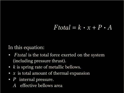
Step 1: Calculate Your Movement Requirements
Axial movement is the change in pipe length due to thermal fluctuations. Before purchasing, you should calculate the required movement using the thermal expansion formula:
Pro Tip: While it’s tempting to choose a joint with a massive safety buffer, an over-specified axial rating can unnecessarily increase costs. Aim for a balance of safety and economic efficiency.
If you are dealing with a system that has significant lateral movement, a single expansion joint may not be sufficient, and you will need to consider other options, such as universal expansion joints. Angular movements can be acceptable for single expansion joints.
When planning your piping system, calculating the exact amount of axial movement is your first and most critical step. Overestimating or underestimating thermal growth can lead to catastrophic buckling or equipment damage. Wondering what this looks like at scale or the math behind it?
See how US Bellows engineers used externally pressurized X-Flex expansion joints to handle a massive 8 inches of axial movement for a sprawling flooring manufacturing facility.
Need to understand the math? Read about the hidden force of axial growth to learn why calculating the correct spring rate is essential to prevent your expanding pipes from destroying delicate equipment like CRAC unit intake valves and flanges.
Step 2: Define Design Conditions & Media
The bellows must withstand your system’s worst-case scenario.
Temperature: Ensure the bellows and end fittings are compatible with the maximum system temperature.
Pressure: The design pressure rating must meet or exceed the maximum operating pressure. Exceeding this limit leads to catastrophic bellows “squirm” or rupture.
Media Type: Are you moving liquids, gases, or abrasives? If your media contains solids or is highly corrosive, you may need a specialized liner or alloy.
Your system’s media dictates everything from material choice to joint lifespan. Standard water is one thing, but what happens when you introduce specialized coolants, abrasive catalysts, or high-purity medical gases? You must match your bellows material to the exact chemistry and temperature of your fluid to prevent premature degradation.
Dive into our engineering guide to learn why transitioning to modern dielectric fluids requires upgrading from standard elastomers to 300-series stainless steel or Inconel 625 for single-bellows to prevent degradation and fluid creep.
Step 3: Choose Your End Fittings
End fittings determine how the joint integrates into your existing infrastructure:
Fitting Type
Best For…
Key Benefit
Weld Ends
Permanent installations
Strong, leak-proof, and maintenance-free
Flanges
Systems requiring frequent service
Easy installation and removal
Threaded Ends
Small-diameter piping
Simple, tool-based connection
While the bellows flex, your end fittings keep everything securely connected. Selecting the right materials for your flanges and liners can make or break your budget and your system’s structural integrity.
Read this case study to see strategic material selection in action. See how we engineered the bellows and internal liner from 304L stainless steel for maximum corrosion resistance, while using carbon steel flanges to maintain structural strength and cost efficiency.
Step 4: Don’t Overlook Tie Rods & Control Rods
In high-pressure systems, internal pressure creates pressure thrust: a force that wants to pull the pipe anchors apart.
Tie Rods: These are essential for containing pressure thrust. Without them, the force can cause the bellows to over-extend and fail.
Control Rods: These limit the joint’s movement to a specific range, preventing damage from over-compression or over-extension.
The Rule of Thumb: Unless your anchors are specifically designed to handle full pressure thrust, always specify tie rods.
When using single expansion joints to absorb straight-line axial movement, you cannot afford to ignore internal system pressure. Without the right constraining hardware, such as control or tie rods, unmanaged pressure thrust can cause your bellows to overextend or transfer massive forces directly onto your equipment, overloading your anchors and causing catastrophic leaks.
Discover the high stakes of line pressure thrust in massive utility tunnels. This resource highlights how properly engineering your expansion joints protects expensive pumps, turbines, and anchors from the severe forces of line pressure thrust and thermal stress, ensuring that a pipe doesn’t rupture and shut down critical infrastructure.
Step 5: Select Performance Accessories
To extend the life of your expansion joint, consider these add-ons:
Internal Liners: These reduce turbulence and protect the bellows from abrasive wear in high-velocity systems.
External Covers: Also known as shrouds, these protect the delicate bellows from weld spatter, mechanical impact, and environmental debris.
Sometimes a standard expansion joint isn’t enough for extreme environments. Adding the right performance accessories, like active leak detection and thermal insulation, can turn a potential unscheduled shutdown into a safely managed maintenance window, protecting your most valuable assets.
Discover how multi-ply and single testable bellows with active “sniffers” (pressure gauges) provide critical leak detection by monitoring the space between plies. You can also learn how internal refractory linings create “Cold Wall” designs that protect outer shells from abrasive catalysts and extreme temperatures exceeding 1200°F
See how US Bellows customized single expansion joints for a demanding chemical plant process. This case study shows performance accessories in action, highlighting how engineers integrated a 304 stainless steel internal liner to protect the internal bellows, along with carbon steel external covers and hardware, enabling safe operation at 145 psig.
Engineering Excellence with US Bellows
When your infrastructure is on the line, off-the-shelf isn’t always enough. US Bellows combines decades of manufacturing experience with cutting-edge engineering to deliver custom solutions.
With our virtual expansion joint inspections, we use digital data collection to offer faster turnarounds and more consistent records, ensuring your system’s health is documented and protected.
Eliminate the Guesswork in Your Pipe Design
Specifying the wrong expansion joint can lead to costly downtime or catastrophic system failure. Don’t leave your thermal expansion calculations to chance.
Our engineering team is ready to review your system specs and provide a precision-engineered solution that meets your exact pressure and temperature requirements. Request aconsultation with a US Bellows engineer.
Single Expansion Joint FAQ
What happens if I install an expansion joint without tie rods?
If the system pressure is high and the anchors are insufficiently reinforced, the thrust from the pressure can cause the expansion joint to extend fully, potentially damaging the bellows or pulling the piping off its supports.
When should I use a stainless steel bellows versus a nickel alloy?
Stainless steel (like 304 or 316) is excellent for general corrosion resistance. However, in high-chloride environments, corrosive environments, or at extreme temperatures (above 1200°F), nickel alloys such as Inconel® or Hastelloy® may be required to prevent stress corrosion cracking.
These are only a couple of considerations, and each application is different and unique. Reach out to US Bellows to discuss your application, and our team of engineers can help you choose the material that best suits your application.
Does insulation affect expansion joint performance?
Yes. If you insulate over an expansion joint, the insulation must be designed to be “removable” or flexible. Rigid insulation can pack into the bellows’ convolutions, preventing bellows movement and causing issues with the equipment or pipe supports.
Flanges and Expansion Joints: An Essential Relationship in Piping Design
Metal flanges are a cornerstone of modern industrial piping systems, but their role extends beyond just connecting pipes. They are an essential, pressure-resistant component of expansion joints, which manage thermal movement and stress in piping systems. Industrial piping designers need to understand and focus on the cooperative relationship between metal flanges and expansion joints.
The Role of Flanges in Piping Systems
Metal flanges, in layman’s terms, are rings with holes (for bolting) that create secure, leak-proof connections between pipes, valves, and other equipment. They are essential for:
Reliability & Durability: Made from high-strength materials such as carbon and stainless steel, flanges withstand extreme pressures and temperatures.
Leak Prevention: When paired with gaskets and properly bolted, they form a tight seal, preventing the escape of fluids and gases.
Maintenance & Flexibility: Flanged connections allow for easy piping assembly and disassembly, simplifying inspections, repairs, and system modifications.
Provide a Secure Connection: Flanges ensure the expansion joint is securely fastened to the adjacent piping. This prevents it from being dislodged by the forces it’s designed to absorb.
Facilitate Installation and Replacement: Using flanges on an expansion joint makes installation and future replacement much simpler and faster than a welded connection. This reduces downtime and labor costs during maintenance.
Ensure System Safety: A well-matched flange connection on an expansion joint ensures that the component can safely handle the system’s pressures and temperatures without leaks.
Common Challenges and Solutions. Even with their durable design, flange connections on expansion joints can face issues. Misalignment and thermal stress are two common culprits. If pipes aren’t correctly aligned before the flange connection is made, it introduces stress on the joint; also, repeated thermal cycles can loosen bolts over time.
To prevent these issues, it is essential to:
Ensure total alignment during installation.
Implement a schedule for periodic bolt retightening in systems that undergo thermal cycles.
By understanding the vital relationship between metal flanges and expansion joints, engineers can design more reliable piping systems. These two components work together to ensure that a system can safely handle the stresses of industrial operations.
Flanges, Welds, and Expansion Joints
While flanges are designed to resist stress, piping systems often undergo significant movement due to temperature fluctuations. This is where expansion joints come in. An expansion joint is a flexible component designed to accommodate thermal expansion and contraction, as well as vibration.
A key point is that the bellows of an expansion joint will either have metal flanges or welded pipe ends to connect to the rest of the piping system. With a flanged connection, assembly and disassembly are easy. Unlike a permanent weld, which requires extensive work and downtime for changes or repair, a flanged joint can be unbolted, allowing for simple inspection, maintenance, and replacement.
When integrated with an expansion joint, flanges can extend beyond static connection points, delivering the versatility they are known for in demanding chemical processing and other mixed-media environments. Here’s a chart that illustrates the difference between a permanent weld (welded attachments) and a flanged connection (flanged attachments).
Weld vs. Flange: A Critical Choice
Consideration
Welded Attachments
Flanged Attachments
Strength
Creates a permanent joint that offers durability and strength. The strength of the joint connection depends on the weld quality.
Depends on proper bolt tightening and gaskets, may be impacted by vibrations and stress
Upfront Cost & Weight
Lower for carbon steels and common stainless steels. The weight will be lower than that of Flange connections.
Higher. As the diameter of the pipe increases, the weight and cost of the Flanges increase
Leak Prevention
Eliminates Leak Paths Associated with Gaskets
Potential for leaks due to gasket degradation or improper installation
Maintenance
Limited ease of maintenance, requires pipe cutting and re-welding for repairs or changes
Easily disassembled for inspections, replacement, or repair, reduced labor and maintenance costs
Installation Cost and Time
Higher initial costs and time due to the need for fitting, welding, and QC inspections of the welds.
Quicker installation and lower up-front costs
Primary Applications
Preferred for corrosive media where a permanent seal works best
Good for environments where welding is not allowed, and regular maintenance is required
Perfect Your Piping Design and Performance….Partner with US Bellows
Are you seeking the ideal expansion joints to complement your flanged piping? Partner with US Bellows. Our expert team specializes in designing and manufacturing top-quality expansion joints that complement your flanged connections.
for a pipeline application in Louisiana. Each expansion joint measures 13.5″ in diameter with a 6″ overall length (OAL). The bellows and internal liner were fabricated from 304L stainless steel to provide enhanced corrosion resistance and durability, while the flanges were constructed from carbon steel for structural strength and cost efficiency.
These expansion joints were engineered to operate at a design temperature of 300°F and a pressure rating of 85 psig. The units were designed to accommodate 1″ of axial compression and 0.10″ of lateral deflection, ensuring the system can safely absorb thermal growth and minor misalignment within the pipeline.
Manufactured to meet design standards such as EJMA, ASME Section VIII, or B31.3 to reinforce engineering credibility, these expansion joints help absorb thermal expansion, reduce stress on piping systems, and extend overall system service life.
To ensure quality and reliability, all expansion joints were hydrostatically tested prior to shipment in accordance with applicable industry standards. This testing verified pressure integrity and overall performance before installation in the field. U.S. Bellows, Inc. specializes in the custom design and manufacture of expansion joints for demanding industrial applications worldwide.
Why Your Chilled Water System Needs Precision Expansion Joints
Thermal Expansion in Chilled Water Loops: Why Precision Matters
In a data center or industrial facility, chilled water loops serve as the primary cooling infrastructure. These systems are dynamic rather than static. When startup sequences or load-shedding events occur, the resulting temperature shifts cause physical changes within the piping. If these movements are not managed, they can lead to severe structural damage.
The Hook: The Hidden Force of Axial Growth
It is a common misconception that cooling systems face fewer expansion challenges than steam systems. While the temperature delta is smaller, the long pipe runs typical of large facilities amplify physical changes. Any rise in temperature will cause the metal to expand. In a straight run of 100 feet, a modest temperature swing can lead to measurable axial growth. Without a designated place for this energy to go, the pipe will find one, often resulting in buckling or severe lateral deflection.
Compensating for Growth with Metallic Expansion Joints
To counteract this movement, engineers integrate metallic expansion joints. Unlike rubber alternatives, metallic bellows offer the longevity and pressure resistance required for high-stakes chilled water environments.
Single bellows expansion joints are the primary solution for absorbing axial movement. As the pipe heats up and grows, the bellows’ thin, convoluted walls compress like an accordion. This prevents the thermal force from transferring further down the line.
In systems with complex routing, universal expansion joints (consisting of two bellows joined by a center pipe) allow for both axial and lateral movement. This is particularly useful when the piping must navigate around structural obstacles while maintaining a constant flow of chilled water.
The Technical Edge: Spring Rate and Flange Protection
Precision in these systems isn’t just about choosing an expansion joint; it is about the math behind the bellows. Every expansion joint has a spring rate, which is the force required to compress the bellows by a specific distance.
If the spring rate is too high, the bellows acts more like a solid pipe than a flexible cushion. When the pipe expands, it pushes against the CRAC (Computer Room Air Conditioning) unit. The delicate intake valves and flanges on a CRAC unit are not designed to be structural anchors. The design engineer needs to consider all the forces involved: pressure thrust, bellows spring-rate force, and any other supports on the piping that affect the CRAC Unit. An overloaded flange can lead to seal failure, leaks, or cracked valve housings. US Bellows engineers calculate these forces to ensure the bellows is flexible enough to protect the equipment while remaining strong enough to contain the system pressure.
Safeguarding Your CRAC Units from Axial Strain with US Bellows
US Bellows provides engineered piping solutions that bridge the gap between theoretical physics and mechanical reliability. By specializing in custom metallic expansion joints, we ensure your mission-critical cooling infrastructure remains stable under shifting thermal loads, preventing costly downtime and equipment failure.
FAQ: Essential Insights on Chilled Water Expansion Joints
How does temperature change affect chilled water piping?
Even in cooling applications, any increase in water temperature causes the metal piping to expand. Because chilled water loops often span long distances, this expansion accumulates into a force that can bend pipes or snap connections at the cooling unit.
Why use metallic bellows instead of rubber connectors?
Metallic bellows provide superior durability and can be custom-engineered with specific spring rates. They are less prone to degradation over time and can handle the pressure surges often found in large-scale chilled water systems.
What happens if the expansion joint spring rate is calculated incorrectly?
If the spring rate is too high, the expansion joint will be stiff and compress only slowly. The force of the expanding pipe will then pass through the joint and “push” on the CRAC unit flange. This can cause the intake valves to warp or leak, leading to system failure.
Can expansion joints handle lateral as well as axial movement?
Yes. While a standard single bellows handles axial (straight-line) growth, a tied universal expansion joint can accommodate lateral offset. This is vital in chilled water layouts where the pipe changes direction near the connection to the cooling unit.
Protect Your CRAC Units with Precision Engineering from US Bellows
Secure your thermal envelope. Protect your cooling assets from the stress of expansion and contraction. Contact the engineering team at US Bellows to request an expansion joint consultation, including custom spring rate analysis, and ensure your CRAC units are protected by the industry’s most reliable metallic expansion joints.
Protecting Hospital Medical Gas Lines with Precision Expansion Joints
Ensuring Uninterrupted Care: The Critical Role of Expansion Joints in Medical Gas Delivery
In a healthcare facility, the medical gas distribution system is the literal lifeline of the building. At any given time, it could be delivering oxygen to an ICU or maintaining the high-flow vacuum required in a surgical suite, and these systems must operate with zero margin for error.
For hospital facility managers, the challenge isn’t just maintaining the gas supply: it’s protecting the rigid piping network from the invisible forces of thermal expansion, mechanical vibration, and seismic activity. This is where precision-engineered expansion joints become critical safeguards.
Engineering for NFPA 99: Material Standards and Pressure Tolerances
Medical gas systems are unique in their material requirements and pressure sensitivities. To maintain gas purity and system integrity, most hospitals utilize ASTM B819 Level L or K degreased copper tubing.
Oxygen and Nitrous Oxide Lines: Typically range from 1/2″ to 4″ in diameter, depending on the distance from the bulk source and the number of terminal units served. These lines must remain free of oils and contaminants to prevent spontaneous combustion.
MRI Equipment: Hospital MRI systems require two kinds of piping systems. Quench Venting systems are safety components in the MRI system. Designed to vent helium gas out of the system during a “quench” event, where the magnet’s cooling system fails and rapidly boils off liquid helium.These lines are 8”-10” NPS Range and made out of stainless steel due to the extreme operating temperature of -270 deg.C.
Medical Vacuum and WAGD (Waste Anesthetic Gas Disposal): Often use larger diameters, often 6″ to 8″ in main headers, to maintain consistent flow rates without pressure drops.
Media Types: These systems transport high-purity oxygen (O2), medical air, nitrous oxide (N2O), nitrogen (N2), and carbon dioxide (CO2). Each has specific pressure profiles and temperature sensitivities that exert stress on the piping joints.
Why Rigid Piping Needs Flexible Solutions
While stainless steel or copper are often the choice for durability in healthcare environments, their thermal expansion coefficient means that long runs of piping will expand and contract as the building’s internal climate or gas temperature fluctuates. Without an expansion joint to absorb this movement, the stress is transferred directly to the brazed joints, leading to hairline fractures and catastrophic leaks.
The NFPA 99 (Health Care Facilities Code) mandates that medical gas systems be protected against physical damage and seismic events. In seismic-prone zones, a rigid pipe can snap during a tremor; a customized metallic expansion joint for seismic activity from US Bellows allows for multi-axial movement, keeping the “lifeline” intact when the building moves.
Selecting the Right Guard: Expansion Joint Types for Healthcare
Hospitals are “Category 1” structures, meaning they must remain functional during and after an earthquake. Universal Gimbal expansion joints use a specialized “ring” harness to allow for angular rotation in any plane.
The Value: They absorb multi-axial movement while resisting pressure thrust, eliminating the need for massive, costly concrete anchors in tight ceiling cavities.
Application: Critical for main headers crossing building expansion joints, to absorb a substantial amount of lateral movement
A hospital’s HVAC system is its lungs. Fabric expansion joints are used in low-pressure air handling units (AHUs).
The Value: They act as vibration breakers, preventing mechanical hum and fan noise from traveling through the ductwork into patient recovery zones.
Application: Large-diameter air intake and exhaust systems.
Hospital Medical Piping: Expansion Joint Selection & Pressure Rating Guide
Application
Recommended Type
Primary Value
Medical Gas / O2
Metallic
Gas purity & high burst pressure (1,000 psi)
MRI Pipelines
Metallic
Chilled water & Helium venting/quenching
Seismic Protection
Universal Gimbal
Multi-axial movement & anchor load reduction
HVAC / Air Ducting
Fabric
Noise reduction & vibration dampening
Sterilization Steam
Metallic
Thermal expansion at 121 °C to 134 °C
The US Bellows Value: Engineering for Zero-Failure Environments
At US Bellows, we understand that hospital infrastructure demands more customization. Our expansion joints for medical gas service are:
Oxygen-Cleaned: Every joint is factory-cleaned and certified for oxygen service, ensuring no hydrocarbons or oils enter your high-purity lines.
Compliance-First: We design in accordance with EJMA standards and facilitate compliance with NFPA 99 requirements for metallic flexible connectors.
Material Integrity: We utilize high-grade stainless steel bellows and bronze or copper end fittings to match the metallurgy of your existing system, preventing galvanic corrosion.
FAQ: Expansion Joints in Healthcare Facilities
What are the NFPA 99 requirements for flexible connectors in medical gas systems?
NFPA 99 requires that flexible connectors be used only where necessary for expansion or vibration control, and that they have a minimum burst pressure of 1,000 psi. They must be made of materials like stainless steel, bronze, or copper that are compatible with the gas being served.
Can rubber expansion joints be used for medical oxygen lines?
Generally, no. For high-purity medical gases, metal bellows (typically stainless steel) are preferred because they are non-permeable and can be easily degreased and cleaned for oxygen service, whereas certain elastomers may degrade or pose a fire risk in high-oxygen environments.
How do expansion joints help with hospital MRI and imaging equipment?
Expansion joints act as vibration isolators. By installing them on the HVAC and chilled water lines serving imaging suites, you prevent mechanical vibrations from the plant room from reaching sensitive diagnostic equipment, which could otherwise cause “noise” in imaging results.
What is the typical lifespan of a metal expansion joint in a hospital setting?
When properly engineered and installed, a high-quality metal expansion joint can last 20 years or more. However, regular inspections every 3–5 years are recommended to detect signs of fatigue or corrosion, especially in steam-intensive environments such as sterilization centers.
Why are chiller water lines in imaging suites typically constructed from non-ferrous materials like copper or stainless steel?
Precision medical imaging equipment, such as MRI machines, relies on powerful and highly sensitive magnetic fields. To ensure the accuracy of these diagnostics, the surrounding infrastructure must not create magnetic interference.
We use non-ferrous metals (typically in the 2” NPS range) for chiller water piping because they are non-magnetic. Using stainless steel or copper prevents the piping from “tugging” on or distorting the machine’s magnetic field. Because these metals have different thermal expansion rates than standard carbon steel, integrating precision expansion joints is critical to absorb thermal movement without risking leaks or mechanical stress near the sensitive equipment.
Secure Your Hospital’s Infrastructure Today
Don’t wait for a “Code Red” leak to evaluate your system’s flexibility. If you are upgrading an existing wing or designing a new surgical center, our engineers can provide a custom assessment of your medical gas piping needs.

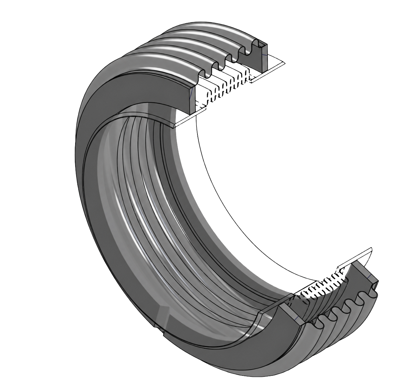
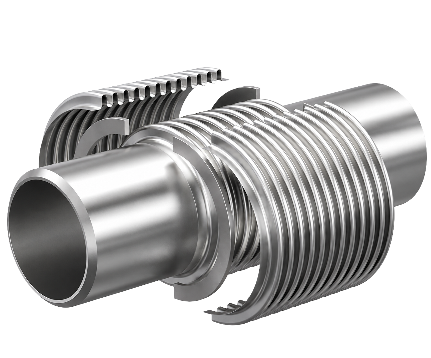
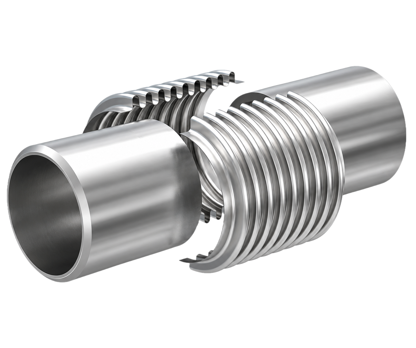

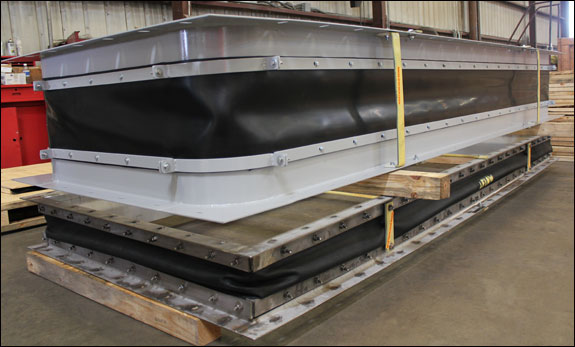
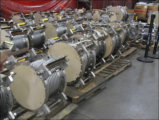
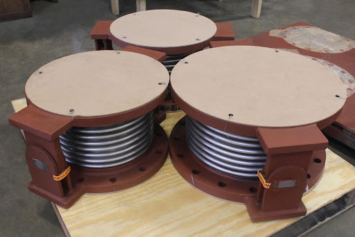
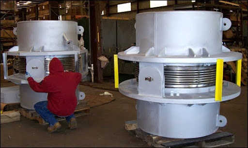
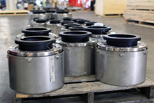
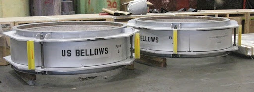
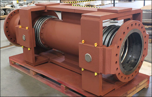
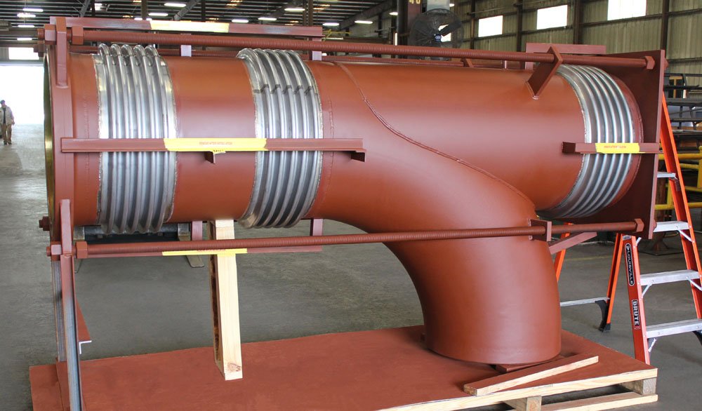
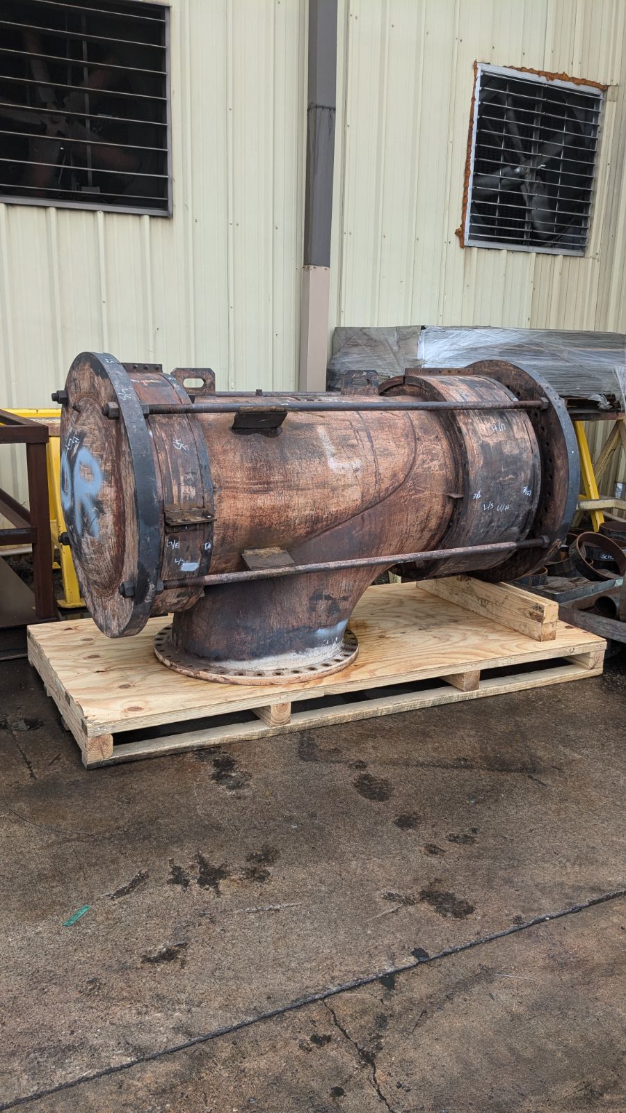
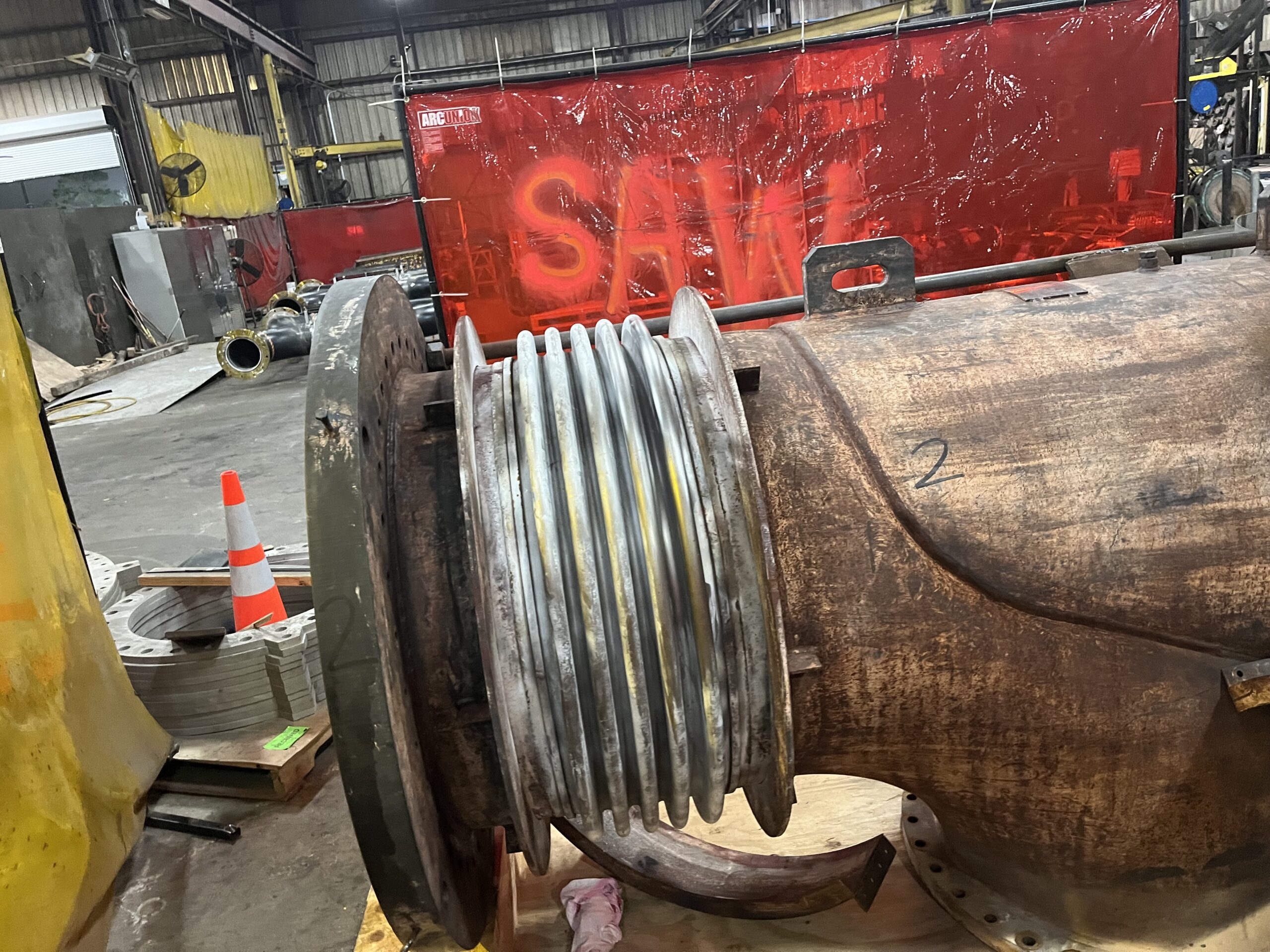
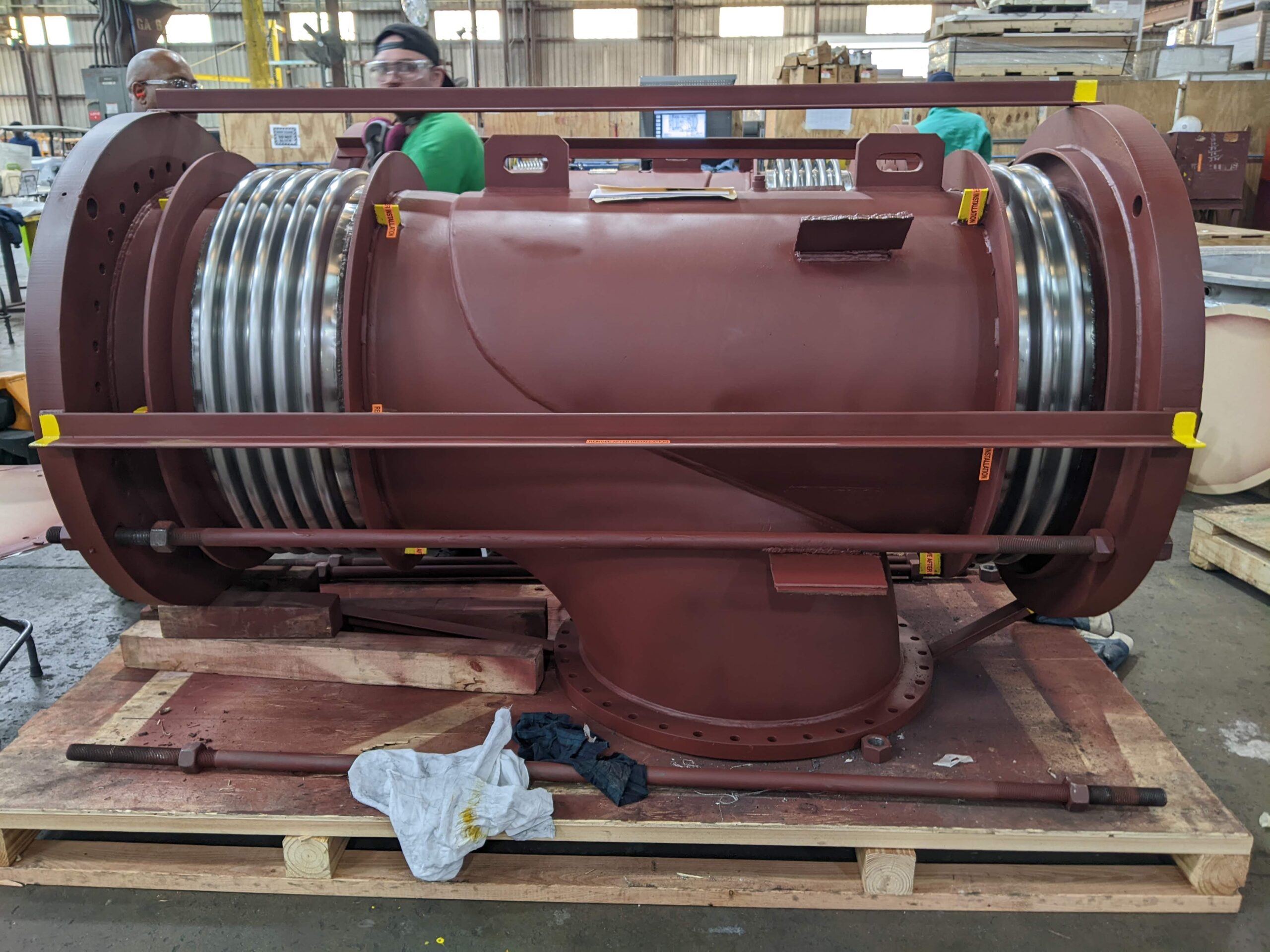
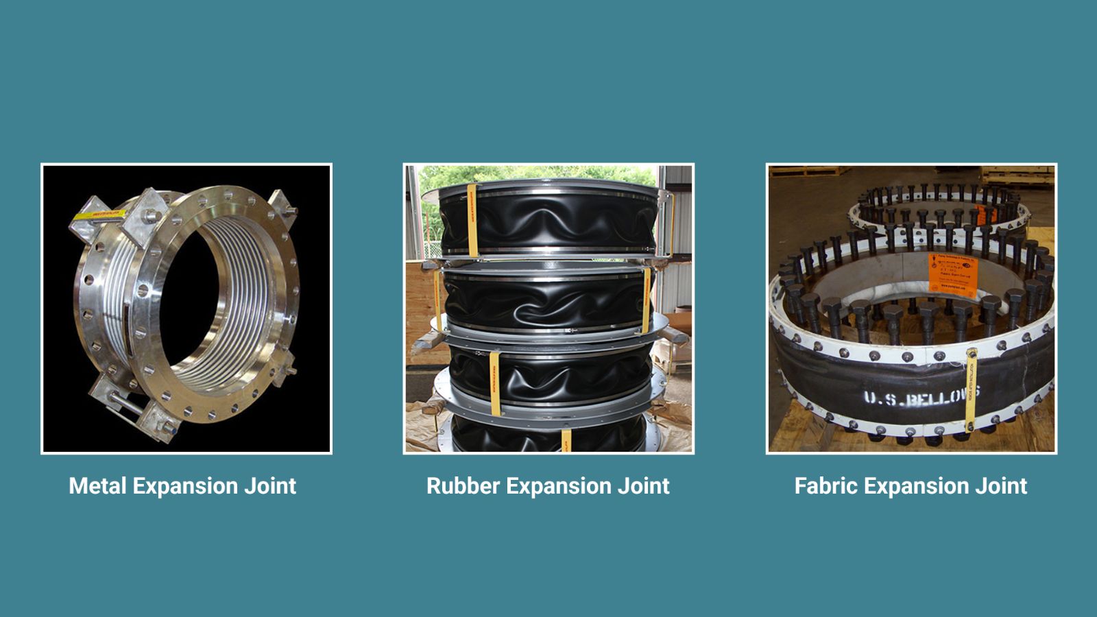
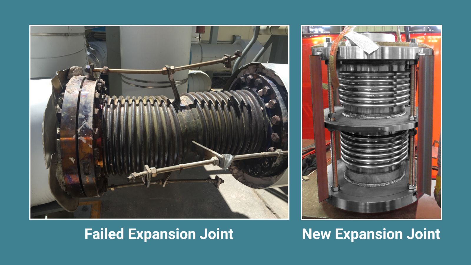
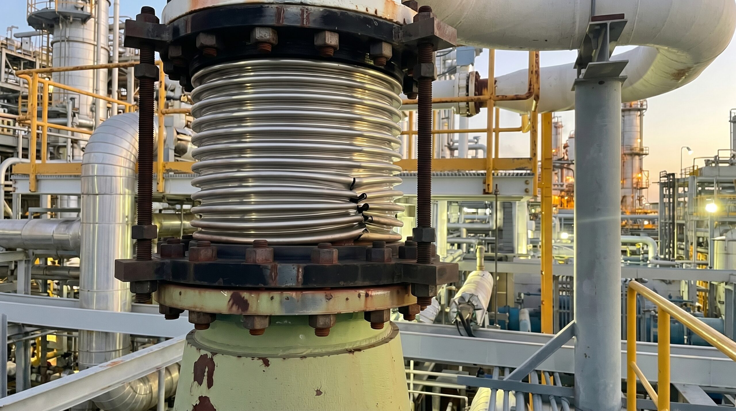

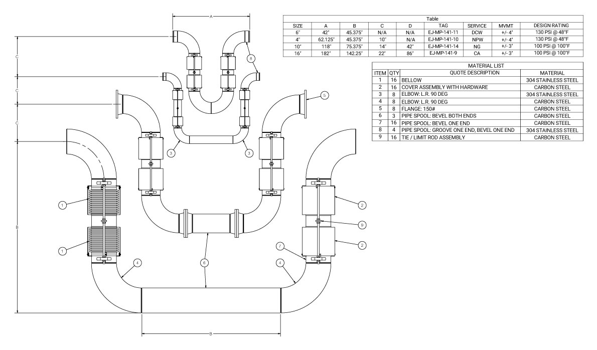
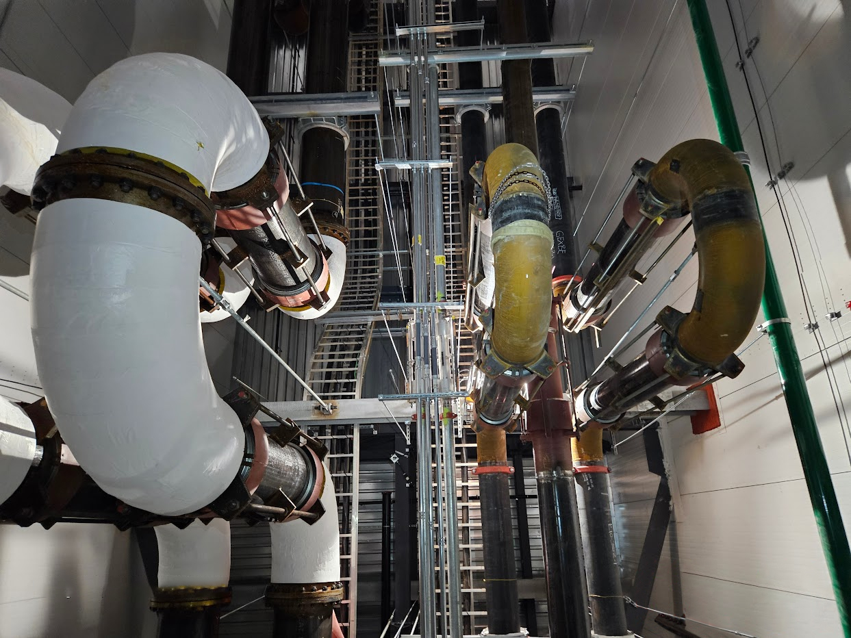
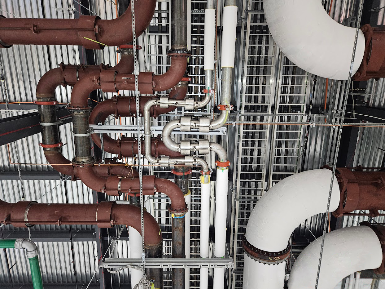

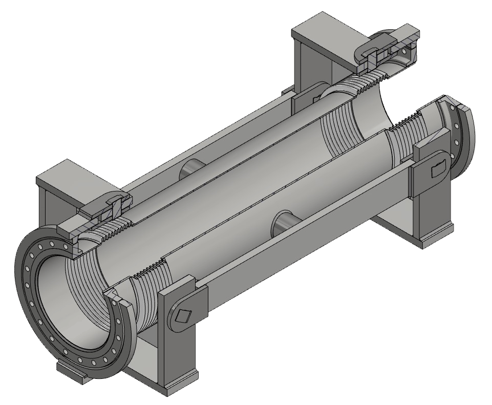
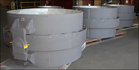
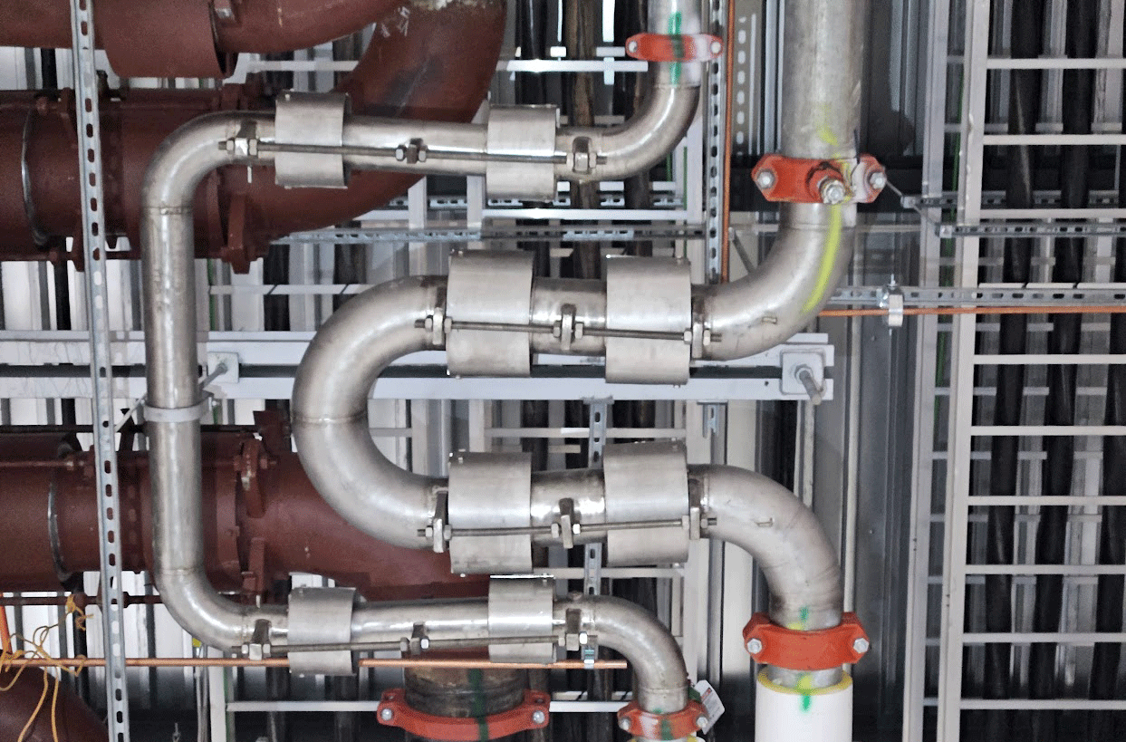

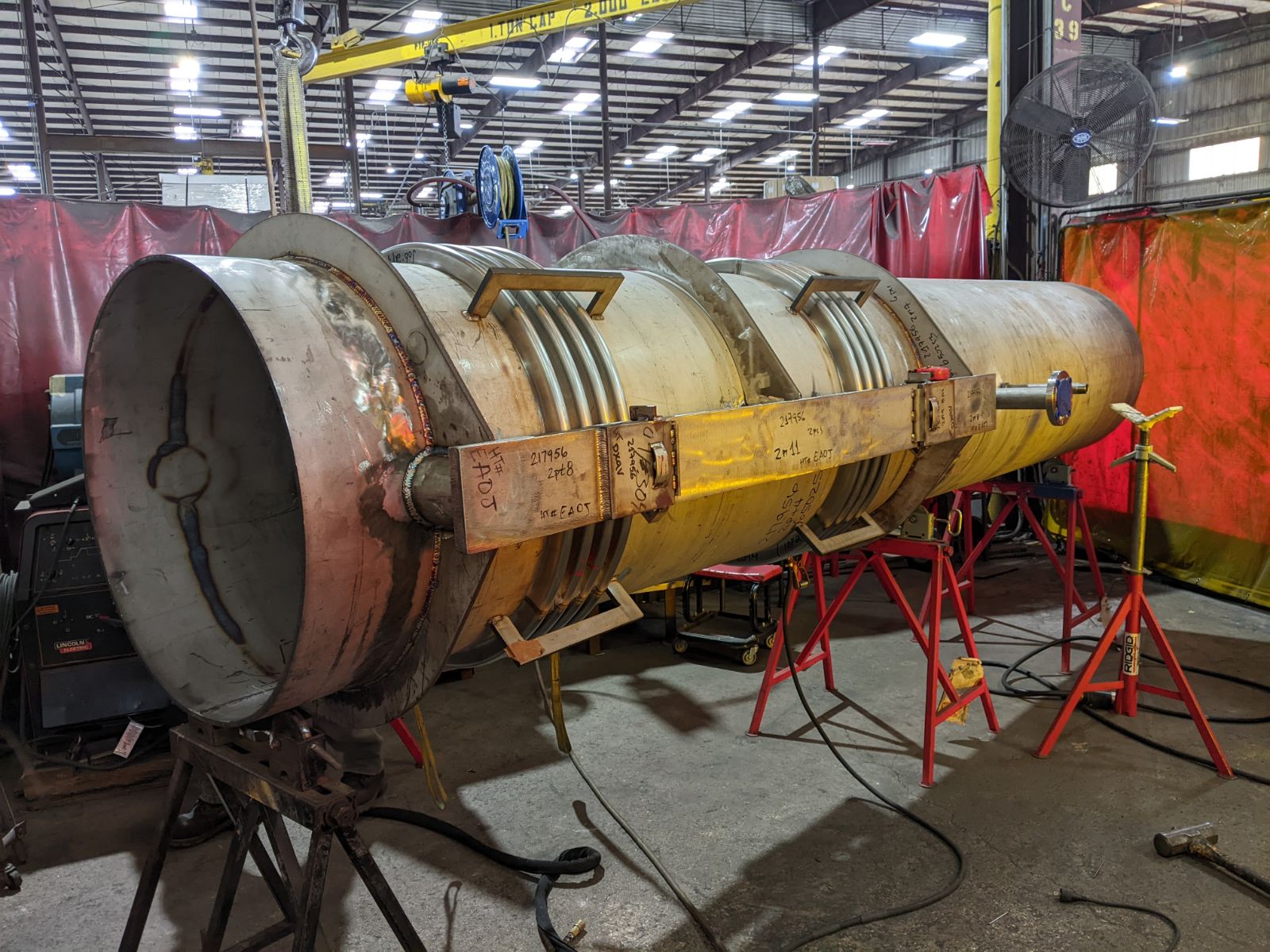
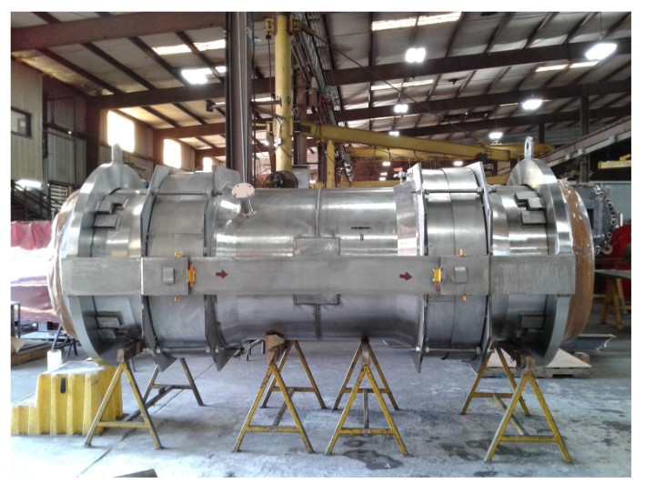
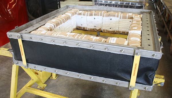
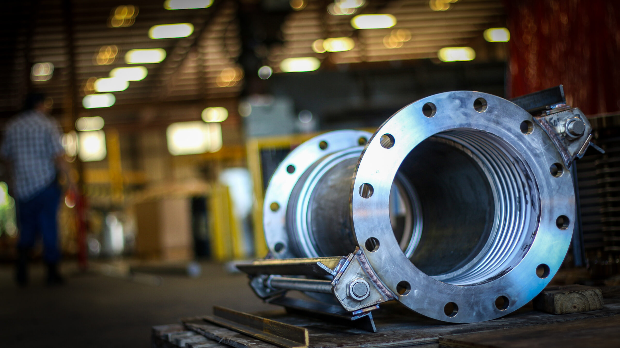 In a complex piping system, the smallest component often carries the heaviest burden. A
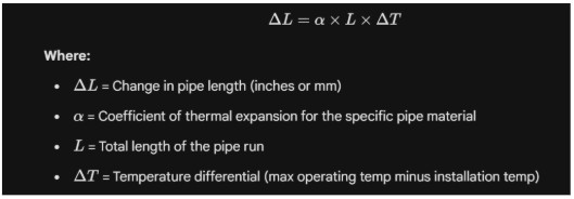
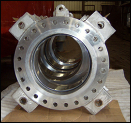 Metal flanges are a cornerstone of modern industrial piping systems, but their role extends beyond just connecting pipes. They are an essential, pressure-resistant component of expansion joints, which manage thermal movement and stress in piping systems. Industrial piping designers need to understand and focus on the cooperative relationship between
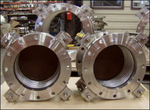 While
While