In a BEM heat exchanger (or any other TEMA shell and tube heat exchanger), the tubes heat up faster and operate at higher temperatures than the outer shell, creating differential thermal expansion that must be properly accommodated to prevent severe stress, leaks in the tubes, and system failure. At US Bellows, we engineer both heavy-wall and thin-wall heat exchanger shell bellows to manage this axial deflection reliably. Heavy-wall bellows offer exceptional durability with wall thickness comparable to the shell itself, while thin-wall designs provide superior flexibility and comparable lifespan through circumferential weld-free construction. Both types are designed per ASME Section VIII B&PV code, with full quality documentation and authorized inspector U2A Partial data report sign-off, ensuring compliance and performance.
Accommodating Thermal Expansion in Heat Exchangers
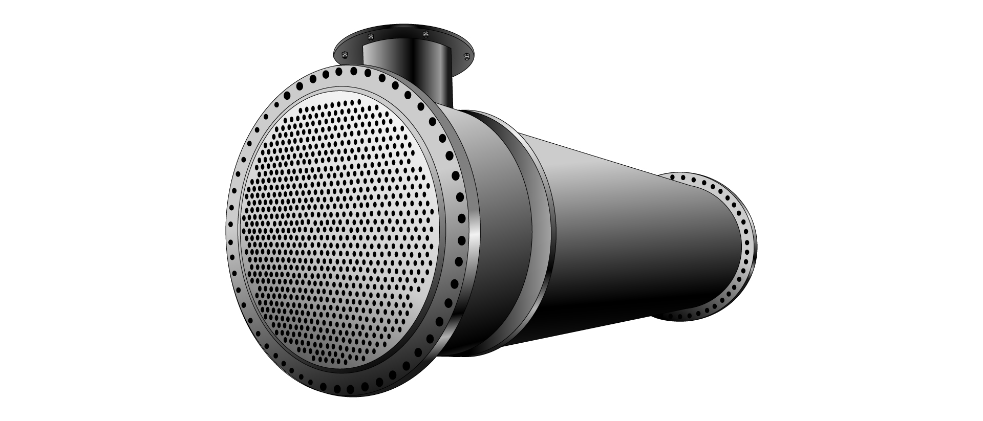
In critical industrial applications, heat exchanger shell bellows are designed to manage the significant change in length called axial deflection, caused by different thermal expansion that takes place between the shell and tubes.
In a shell and tube heat exchanger, the tubes inside heat up faster and operate at higher temperatures than the outer shell. Our heat exchanger shell bellows are flexible components built into heat exchangers to accommodate the thermal expansion and contraction that occur due to the specific design of these heat exchangers.
This differential movement, if not properly accommodated, can lead to severe stresses, potential leaks, and ultimately, system failure.
Choosing the Right Heat Exchanger Shell Bellows: Heavy Wall Bellows vs. Thin Wall Bellows
Selecting the optimal bellows for a shell-and-tube heat exchanger is crucial for ensuring long-term performance and safety.
US Bellows offers two primary types, each with distinct advantages:
- Heavy Wall Bellows: These robust bellows feature a wall thickness comparable to the heat exchanger shell itself, making them incredibly durable and often eliminating the need for an external cover.
Formed by welding flanged and flued plates, they are built to withstand demanding conditions, though a drain might be necessary for trapped fluids. - Thin Wall Heat Exchanger Bellows: Characterized by many small corrugations in the bellows and often reinforced with rings for higher pressure capabilities, these bellows offer superior flexibility and a more compact design. Their construction avoids welds around the circumference of the bellows, which contributes to a longer lifespan. An external cover is typically required for mechanical protection.
Both thick- and thin-wall expansion joints can provide reliable performance in shell and tube heat exchangers. However, it is important to note that the hydrostatic pressure and load (PA load) are carried by the tubes, which function like tie rods.
Both thick and thin expansion joints manufactured by US Bellows are designed per the ASME Section VIII code. Heavy-wall bellows are designed per ASME Section VIII, Div. 1 Appendix CC, and thin-wall bellows per Appendix 26 and need an ASME U-stamp to undergo stringent ASME Code inspections.
It is only after passing the pressure testing and a thorough review of the quality documents and design calculations that the expansion joints receive the ASME stamp, as well as the U-2 manufacturer’s partial data report, duly signed by the ASME Authorized Inspector, affirming their compliance with the highest industry standards.
Precision Engineering & Quality for Heat Exchanger Components
Our commitment to excellence in heat exchanger bellows components is rooted in advanced engineering and rigorous quality control. US Bellows’ engineering processes adhere to the latest revisions of EJMA standards, ASME B31.3, ASME B31.1, and ASME Section 8, Division 1 & 2, utilizing proprietary in-house software and finite element analysis (FEA) for precise design.
Our comprehensive quality assurance program includes extensive in-process and final inspections, with capabilities for Helium, Hydro, X-Ray, and Dye Penetrant testing to guarantee the integrity and performance of every bellows used in shell and tube heat exchangers. Trust our experienced team to deliver superior solutions tailored to your specific requirements.
Schedule time with an engineer for a free consultation.
Ready for Reliable Thermal Management? Get a quote for your next heat exchanger project. Request a Quote Today!
Did you know that US Bellows is a Piping Technology Company?
We are proud to be a one-stop solution from expansion joints to pipe supports and engineering services. We work hard to simplify your supply chain, and ensure system reliability with quality assurance.