Request A Quote

Single Expansion Joints – 144 Inch, 156 Inch Nominal Diameter

144 Inch, 156 Inch Nominal Diameter

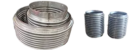
Single Weld End
Single Weld End
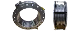
Single Flanged End
Single Flanged End
Single Flanged Weld End

Notes:

  1. Rated life cycle at 650°F is 3000 cycles for any one tabulated movement.
  2. To combine axial, lateral and angular movements, please refer to the how to order section
  3. To increase cycle life or movements, please refer to the graph on cycle life
  4. Rated bellows extension is equal to rated axial movement. Provided bellows is precompressed the amount of design extension. Installed overall length will decrease by the amount of precompression.
  5. Maximum test pressure: 1.5 X rated working pressure.
  6. Bellows rated for 650°F: For appropriate flange temperature/pressure ratings, see catalog flange data
  7. Torsional spring rate data provided only for modeling expansion joints on computer stress programs. Please consult factory for allowable torsional loadings.
  8. Overall lengths and weights for unrestrained expansion joints only. Consult factory for information regarding tied, hinged, or gimbal expansion joints.
  9. Pressure thrust load applied to adjacent pipe anchors/equipment when unrestrained expansion joints are used.


Dia.PressureOverall Length and WeightNon-concurrant

movements
Spring rates
Flanged

Ends
Weld

Ends
Combination

Ends
AxialLateralAngularAxialLateralAngularTorsional
Overall
Length
WeightOverall
Length
WeightOverall
Length
WeightComp-ression
PSIGin.lb.in.lb.in.lb.in.in.deg.lb./in.lb./in.in./lb./deg.in./lb./deg.

x 106
kg/cm 2mmkgmmkgmmkgmmmmGradkg/mmkg/mmN-M/GradN-M/Grad

x 105
14425Customer to
specify flange 
configuration. 
Weights and
O.A.L. will be
furnished upon
receipt of this 
information.
16570Customer to
specify flange 
configuration. 
Weights and
O.A.L. will be
furnished upon
receipt of this 
information.
2.910.05281244068158378682855.0225
1.740625973.91.2731457280238512869.5578
Effective
Area
247105.820.2154062509520189341427.5112
6103231485.33573910019256434.7789
16,781 in2328508.730.4872708150673126227285.0075
108,264 cm281338622212.2848269612837.3289.8526
15625166383.690.06354013182115296205957.6637
1.740629093.71.523975694630124973.944
Effective
Area
248107.380.2552701397764148102478.8319
6103681876.35648711815062486.972
19,743 in23093910.10.4771964153009107711348.2414
125,632 cm276242725811.9835273810954.2354.1615


Materials
Bellows: A240-T304. Alternate materials available upon request. Refer to the materials section
Flanges: ASTM A105.
Customer to specify actual flanges required.
Pipe: ASTM A285-C.
25 psig Series: 0.375-inch wall.
Liners: A240-T304.
Covers: Carbon steel.
Tie Rods, Hinges, Gimbals: Carbon steel


Single Expansion Joints – 108 Inch, 120 Inch, 132 Inch Nominal Diameter

108 Inch, 120 Inch, 132 Inch Nominal Diameter

Single Weld End
Single Weld End
Single Flanged End
Single Flanged End
Single Flanged Weld End

Notes:

  1. Rated life cycle at 650°F is 3000 cycles for any one tabulated movement.
  2. To combine axial, lateral and angular movements, please refer to the how to order section
  3. To increase cycle life or movements, please refer to the graph on cycle life
  4. Rated bellows extension is equal to rated axial movement. Provided bellows is precompressed the amount of design extension. Installed overall length will decrease by the amount of precompression.
  5. Maximum test pressure: 1.5 X rated working pressure.
  6. Bellows rated for 650°F: For appropriate flange temperature/pressure ratings, see catalog flange data
  7. Torsional spring rate data provided only for modeling expansion joints on computer stress programs. Please consult factory for allowable torsional loadings.
  8. Overall lengths and weights for unrestrained expansion joints only. Consult factory for information regarding tied, hinged, or gimbal expansion joints.
  9. Pressure thrust load applied to adjacent pipe anchors/equipment when unrestrained expansion joints are used.


DiameterPressureOverall Length and WeightNon-concurrant

movements
Spring rates
Flanged

Ends
Weld

Ends
Combination

Ends
AxialLateralAngularAxialLateralAngularTorsional
Overall LengthWeightOverall LengthWeightOverall LengthWeightCompression
PSIGin.lb.in.lb.in.lb.in.in.deg.lb./in.lb./in.in./lb./deg.in./lb./deg.

x 106
kg/cm 2mmkgmmkgmmkgmmmmGradkg/mmkg/mmN-M/GradN-M/Grad

x 105
10835Customer to specify flange configuration Weights and O.A.L. will be furnished upon receipt of this information.16427Customer to specify flange configuration. Weights and O.A.L. will be furnished upon receipt of this information.2.870.07360791729417160982360.953
2.440619472.91.7831093094916371.9367.0892
Effective Area245325.740.286304021617780491180.4765
6102421467.1175438698185.9183.5446
9533 in2326378.60.62920266405253661120.3177
61,505 cm281329021815.7103611465457.3122.3631
12030164752.90.06367612365085220152495.0025
2.140621673.71.5231214232422389.6503.4175
Effective Area245915.790.2553380295636110076247.5012
6102691476.35660529111194.7251.7088
11,723 in2327088.690.57822548759673384165.0008
75,632 cm281332222114.594015687463.2167.8058
13225165222.910.06374423140065292291658.7047
1.740623773.91.5231335619329726669.9027
Effective Area246515.820.2353721392508146145329.3523
6102961485.85667702414862.9334.9513
14,139 in2327798.730.527248111629997430219.5682
91,219 cm281335422213.284420819908.6223.3009


Materials
Bellows: A240-T304. Alternate materials available upon request. Refer to the materials section
Flanges: ASTM A105.
Customer to specify actual flanges required.
Plate flanges and angle flanges available for low pressure systems.
Pipe: ASTM A285-C.
25-35 PSIG Series: 0.375-inch wall.
Liners: A240-T304.
Covers: Carbon steel.
Tie Rods, Hinges, Gimbals: Carbon steel


Single Expansion Joints – 84 Inch, 96 Inch Nominal Diameter

84 Inch, 96 Inch Nominal Diameter

Single Weld End
Single Weld End
Single Flanged End
Single Flanged End
Single Flanged Weld End

Notes:

  1. Rated life cycle at 650°F is 3000 cycles for any one tabulated movement.
  2. To combine axial, lateral and angular movements, please refer to the how to order section
  3. To increase cycle life or movements, please refer to the graph on cycle life
  4. Rated bellows extension is equal to rated axial movement. Provided bellows is precompressed the amount of design extension. Installed overall length will decrease by the amount of precompression.
  5. Maximum test pressure: 1.5 X rated working pressure.
  6. Bellows rated for 650°F: For appropriate flange temperature/pressure ratings, see catalog flange data
  7. Torsional spring rate data provided only for modeling expansion joints on computer stress programs. Please consult factory for allowable torsional loadings.
  8. Overall lengths and weights for unrestrained expansion joints only. Consult factory for information regarding tied, hinged, or gimbal expansion joints.
  9. Pressure thrust load applied to adjacent pipe anchors/equipment when unrestrained expansion joints are used.


DiameterPressureOverall Length and WeightNon-concurrant

movements
Spring rates
Flanged

Ends
Weld

Ends
Combination

Ends
AxialLateralAngularAxialLateralAngularTorsional
O.A.LWT.O.A.LWT.O.A.LWT.Compression
PSIGINLBINLBINLBININDEGLB/INLB/ININ-LB/DEGIN-LB/DEG

x 106
KG/CM2MMKGMMKGMMKGMMMMGRADKG/MMKG/MMN-M/GRADN-M/GRAD

x 105
8445142089163321512102.820.094471682080476404169.9604
3.135695040615138155071.62.29484146897770.3172.8497
Effective Area222171244142312925.650.35823581026013820284.9802
5599876101885845871448.8984218363885.186.4249
16,781 in2302252324953113748.470.79101572304002546856.6535
108,264 cm2762102481322578762521520.111285442590.157.6166
9640143400163781518892.730.07353981387244113494257.6974
2.8356154640617238185969.31.784972482511542.3262.0783
Effective Area223494244712319825.560.297269916239956747127.8144
55915886102145849011417.3774829065771.2129.9873
19,743 in2303587325653120768.350.67101799471003783184.9823
125,632 cm276216308142577879442121711328433847.486.427

nbsp;

Materials
Bellows: A240-T304. Alternate materials available upon request. Refer to the materials section
Flanges: ASTM A105.
40-45 PSIG Series: 125 lb. Lt. Wt. FFSO
Plate flanges and angle flanges available for low pressure systems.
Pipe: ASTM A285-C.
40-45 PSIG Series: 0.375-inch wall.
Liners: A240-T304.
Covers: Carbon steel.
Tie Rods, Hinges, Gimbals: Carbon steel


Single Expansion Joints – 60 Inch, 66 Inch, 72 Inch Nominal Diameter

60 Inch, 66 Inch, 72 Inch Nominal Diameter

Single Weld End
Single Weld End
Single Flanged End
Single Flanged End
Single Flanged Weld End

Notes:

  1. Rated life cycle at 650°F is 3000 cycles for any one tabulated movement.
  2. To combine axial, lateral and angular movements, please refer to the how to order section
  3. To increase cycle life or movements, please refer to the graph on cycle life
  4. Rated bellows extension is equal to rated axial movement. Provided bellows is precompressed the amount of design extension. Installed overall length will decrease by the amount of precompression.
  5. Maximum test pressure: 1.5 X rated working pressure.
  6. Bellows rated for 650°F: For appropriate flange temperature/pressure ratings, see catalog flange data
  7. Torsional spring rate data provided only for modeling expansion joints on computer stress programs. Please consult factory for allowable torsional loadings.
  8. Overall lengths and weights for unrestrained expansion joints only. Consult factory for information regarding tied, hinged, or gimbal expansion joints.
  9. Pressure thrust load applied to adjacent pipe anchors/equipment when unrestrained expansion joints are used.


DiameterPressureOverall Length and WeightNon-concurrant

movements
Spring rates
Flanged

Ends
Weld

Ends
Combination

Ends
AxialLateralAngularAxialLateralAngularTorsional
Overall LengthWeightOverall LengthWeightOverall LengthWeightCompression
PSIGin.lb.in.lb.in.lb.in.in.deg.lb./in.lb./in.in./lb./deg.in./lb./deg.

x 106
kg/cm 2mmkgmmkgmmkgmmmmGradkg/mmkg/mmN-M/GradN-M/Grad

x 105
606013134316236157892.650.11533533456652828063.0276
4.233061040610738135967.32.7956061862876.164.0991
Effective Area21140124294238485.310.44101677404651414031.2608
53363761013458438513511.21130724143831.7923
3036 in229145932353319068.141.0310111811736942720.785
19,587 cm273766381316078741220726.21120210958.721.1383
665513156916260159142.670.1536944578203745583.8532
3.833071340611838141567.82.5456681933809.285.2787
Effective Area21163324324239785.450.4191847535951872841.5901
5337426101475844451.3810.410339591904.642.2971
3650 in2291697323883110438.170.94101231155441248527.6527
23,550 cm273777181317678747420823.911222781269.728.1228
7250131775162831510292.70.094403559193448428108.8247
3.533080740612938146868.62.29572105934925.1110.6748
Effective Area21184524532310995.510.3892017692952421453.9756
5338396101605845001409.6593612402462.654.8932
4321 in2291915324233111698.260.87101345200971614335.8877
27,877 cm273787081319278753121022.111243601641.736.4978


Materials
Bellows: A240-T304. Alternate materials available upon request. Refer to the materials section
Flanges: ASTM A105.
50-60 PSIG Series: 125 lb. Lt. Wt. FFSO.
Plate flanges and angle flanges available for low-pressure systems.
Pipe: ASTM A285-C.
50-60 PSIG Series: 0.375-inch wall.
Liners: A240-T304.
Covers: Carbon steel.
Tie Rods, Hinges, Gimbals: Carbon steel


Single Expansion Joints – 50 Inch, 52 Inch, 54 Inch Nominal Diameter

50 Inch, 52 Inch, 54 Inch Nominal Diameter

Single Weld End
Single Weld End
Single Flanged End
Single Flanged End
Single Flanged Weld End

Notes:

  1. Rated life cycle at 650°F is 3000 cycles for any one tabulated movement.
  2. To combine axial, lateral and angular movements, please refer to the how to order section
  3. To increase cycle life or movements, please refer to the graph on cycle life
  4. Rated bellows extension is equal to rated axial movement. Provided bellows is precompressed the amount of design extension. Installed overall length will decrease by the amount of precompression.
  5. Maximum test pressure: 1.5 X rated working pressure.
  6. Bellows rated for 650°F: For appropriate flange temperature/pressure ratings, see catalog flange data
  7. Torsional spring rate data provided only for modeling expansion joints on computer stress programs. Please consult factory for allowable torsional loadings.
  8. Overall lengths and weights for unrestrained expansion joints only. Consult factory for information regarding tied, hinged, or gimbal expansion joints.
  9. Pressure thrust load applied to adjacent pipe anchors/equipment when unrestrained expansion joints are used.


DiaPressureOverall Length and WeightNon-concurrant

movements
Spring rates
Flanged

Ends
Weld

Ends
Combination

Ends
AxialLateralAngularAxialLateralAngularTorsional
Overall LengthWeightOverall LengthWeightOverall LengthWeightCompression
PSIGin.lb.in.lb.in.lb.in.in.deg.lb./in.lb./in.in./lb./deg.in./lb./deg.

x 106
kg/cm 2mmkgmmkgmmkgmmmmGradkg/mmkg/mmN-M/GradN-M/Grad

x 105
50751395316197155752.10.1152786177720164335.9278
5.233043340689.538126153.32.7955031801682.436.5386
Effective Area21100224246236245.40.5510139322215827117.9639
533455610112584284137141125398841.218.2693
2138 in229105032294316728.11.24109296582551411.9759
13,792 cm273747781313478730520631.51117118560.812.1795
527013100516205156052.720.13628991994151856240.405
4.933045740693.238127669.13.365235691887.841.0919
Effective Area21105624256236565.440.5410145024927928120.2025
53348061011658429813813.71126446943.920.5459
2305 in229110632306317068.161.2109667386618713.4683
14,870 cm273750381313978732120730.51117132629.213.6973
547013105716213156352.720.13630132228072074045.2394
4.933048040696.838128969.13.365439872109.346.0085
Effective Area21111024266236885.440.52101506278511037022.6197
53350561012158431313813.211274981054.623.0043
2478 in229116232318317408.151.161010048252691315.0798
15,989 cm273752881314578733620729.51118148703.115.3362


Materials
Bellows: A240-T304. Alternate materials available upon request. Refer to the materials section
Flanges: ASTM A105.
70-75 PSIG Series: 125 lb. Lt. Wt. FSSO.
Plate flanges and angle flanges available for low pressure systems.
Pipe: ASTM A285-C.
70-75 PSIG Series: 0.375-inch wall.
Liners: A240-T304.
Covers: Carbon steel.
Tie Rods, Hinges, Gimbals: Carbon steel


Single Expansion Joints – 48 Inch Nominal Diameter

48 Inch Nominal Diameter

Effective (Thrust) Area: 1947 in2 (12,561 cm2)

Single Weld End
Single Weld End
Single Flanged End
Single Flanged End
Single Flanged Weld End

Notes:

  1. Rated life cycle at 650°F is 3000 cycles for any one tabulated movement.
  2. To combine axial, lateral and angular movements, please refer to the how to order section
  3. To increase cycle life or movements, please refer to the graph on cycle life
  4. Rated bellows extension is equal to rated axial movement. Provided bellows is precompressed the amount of design extension. Installed overall length will decrease by the amount of precompression.
  5. Maximum test pressure: 1.5 X rated working pressure.
  6. Bellows rated for 650°F: For appropriate flange temperature/pressure ratings, see catalog flange data
  7. Torsional spring rate data provided only for modeling expansion joints on computer stress programs. Please consult factory for allowable torsional loadings.
  8. Overall lengths and weights for unrestrained expansion joints only. Consult factory for information regarding tied, hinged, or gimbal expansion joints.
  9. Pressure thrust load applied to adjacent pipe anchors/equipment when unrestrained expansion joints are used.


DiaPressureOverall Length and WeightNon-concurrant

movements
Spring rates
Flanged

Ends
Weld

Ends
Combination

Ends
AxialLateralAngularAxialLateralAngularTorsional
Overall LengthWeightOverall LengthWeightOverall LengthWeightCompression
PSIGin.lb.in.lb.in.lb.in.in.deg.lb./in.lb./in.in./lb./deg.in./lb./deg.

x 106
kg/cm 2mmkgmmkgmmkgmmmmGradkg/mmkg/mmN-M/GradN-M/Grad

x 105
48351289116179145353.290.15867050793362015.2078
2.530540540681.435624383.63.81812909368.215.4663
351892322212205676.110.5310361793019498.1888
2.545742055996.450825815513.5116142198.28.328
352294526233245897.990.9110276354614916.262
2.555943065010661026820323.111563151.66.3685
4895Customer to specify flange configuration. Weights and O.A.L. will be furnished upon receipt of this information.16203Customer to specify flange configuration. Weights and O.A.L. will be furnished upon receipt of this information.2.550.12627442083211484724.6308
6.740692.364.83.0574937281509.925.0495
95222254.730.4110147832523799413.2627
6.755911612010.4112658281313.4882
95262896.190.710113014544611310.1421
6.766013115717.81120260621.710.3145


Materials
Bellows: A240-T304. Alternate materials available upon request. Refer to the materials section
Flanges: ASTM A105.
35 PSIG Series: 125 lb. Lt. Wt. FFSO.
95 PSIG Series: Customer to specify actual flanges required.
Plate flanges and angle flanges available for low pressure systems.
Pipe: ASTM A285-C.
35 PSIG Series: 0.375-inch wall.
95 PSIG Series: 0.375-inch wall.
Liners: A240-T304.
Covers: Carbon steel.
Tie Rods, Hinges, Gimbals: Carbon steel


Single Expansion Joints – 46 Inch Nominal Diameter

46 Inch Nominal Diameter

Effective (Thrust) Area: 1794 in2 (11,575 cm2)

Single Weld End
Single Weld End
Single Flanged End
Single Flanged End
Single Flanged Weld End

Notes:

  1. Rated life cycle at 650°F is 3000 cycles for any one tabulated movement.
  2. To combine axial, lateral and angular movements, please refer to the how to order section
  3. To increase cycle life or movements, please refer to the graph on cycle life
  4. Rated bellows extension is equal to rated axial movement. Provided bellows is precompressed the amount of design extension. Installed overall length will decrease by the amount of precompression.
  5. Maximum test pressure: 1.5 X rated working pressure.
  6. Bellows rated for 650°F: For appropriate flange temperature/pressure ratings, see catalog flange data
  7. Torsional spring rate data provided only for modeling expansion joints on computer stress programs. Please consult factory for allowable torsional loadings.
  8. Overall lengths and weights for unrestrained expansion joints only. Consult factory for information regarding tied, hinged, or gimbal expansion joints.
  9. Pressure thrust load applied to adjacent pipe anchors/equipment when unrestrained expansion joints are used.


DiaPressureOverall Length and WeightNon-concurrant

movements
Spring rates
Flanged

Ends
Weld

Ends
Combination

Ends
AxialLateralAngularAxialLateralAngularTorsional
Overall LengthWeightOverall LengthWeightOverall LengthWeightCompression
PSIGin.lb.in.lb.in.lb.in.in.deg.lb./in.lb./in.in./lb./deg.in./lb./deg.

x 106
kg/cm 2mmkgmmkgmmkgmmmmGradkg/mmkg/mmN-M/GradN-M/Grad

x 105
46351277416176144753.510.18856134157279411.8403
2.53053524068035621689.24.57910611284.112.0416
351880522207205066.330.610321602415976.7347
2.545736655994.150823016115.2116108162.46.8492
352282626228245278.21110249278812425.2309
2.555937566010461024020925.411450126.35.3199
4695Customer to specify flange configuration. Weights and O.A.L. will be furnished upon receipt of this information.16202Customer to specify flange configuration. Weights and O.A.L. will be furnished upon receipt of this information.2.840.15723001400961146219.1806
6.740691.872.13.8184125071165.719.5067
95222515.10.4810131424708654910.9093
6.755911413012.2112444266611.0848
95262846.550.81010221143650948.4734
6.766012916620.31118205518.18.6174


Materials
Bellows: A240-T304. Alternate materials available upon request. Refer to the materials section
Flanges: ASTM A105.
35 PSIG Series: 125 lb. Lt. Wt. FFSO.
95 PSIG Series: Customer to specify actual flanges required.
Plate flanges and angle flanges available for low pressure systems.
Pipe: ASTM A285-C.
35 PSIG Series: 0.375-inch wall.
95 PSIG Series: 0.375-inch wall.
Liners: A240-T304.
Covers: Carbon steel.
Tie Rods, Hinges, Gimbals: Carbon steel


Single Expansion Joints – 44 Inch Nominal Diameter

44 Inch Nominal Diameter

Effective (Thrust) Area: 1629 in2 (10,508 cm2)

Single Weld End
Single Weld End
Single Flanged End
Single Flanged End
Single Flanged Weld End

Notes:

  1. Rated life cycle at 650°F is 3000 cycles for any one tabulated movement.
  2. To combine axial, lateral and angular movements, please refer to the how to order section
  3. To increase cycle life or movements, please refer to the graph on cycle life
  4. Rated bellows extension is equal to rated axial movement. Provided bellows is precompressed the amount of design extension. Installed overall length will decrease by the amount of precompression.
  5. Maximum test pressure: 1.5 X rated working pressure.
  6. Bellows rated for 650°F: For appropriate flange temperature/pressure ratings, see catalog flange data
  7. Torsional spring rate data provided only for modeling expansion joints on computer stress programs. Please consult factory for allowable torsional loadings.
  8. Overall lengths and weights for unrestrained expansion joints only. Consult factory for information regarding tied, hinged, or gimbal expansion joints.
  9. Pressure thrust load applied to adjacent pipe anchors/equipment when unrestrained expansion joints are used.


DiaPressureOverall Length and WeightNon-concurrant

movements
Spring rates
Flanged

Ends
Weld

Ends
Combination

Ends
AxialLateralAngularAxialLateralAngularTorsional
Overall LengthWeightOverall LengthWeightOverall LengthWeightCompression
PSIGin.lb.in.lb.in.lb.in.in.deg.lb./in.lb./in.in./lb./deg.in./lb./deg.

x 106
kg/cm 2mmkgmmkgmmkgmmmmGradkg/mmkg/mmN-M/GradN-M/Grad

x 105
44501273716164144503.510.19985447202386211.8051
3.530533540674.535620589.24.831015845392.812.0058
501876320190144776.330.6310488832522076.7104
3.545734750886.435621716116119149224.56.8245
502479028216265039.151.3110342279315454.6874
3.561035971198.266022923233.311650157.14.7671
44115Customer to specify flange configuration. Weights and O.A.L. will be furnished upon receipt of this information.16185Customer to specify flange configuration. Weights and O.A.L. will be furnished upon receipt of this information.2.250.12635001936141584019.1526
8.140684.157.23.0566334651610.919.4782
115222273.940.3910200034147905110.8863
8.15591031009.911136611920.511.0713
115282555.060.651015551571570408.4492
8.171111612916.5112817168.5928


Materials
Bellows: A240-T304. Alternate materials available upon request. Refer to the materials section
Flanges: ASTM A105.
50 PSIG Series: 125 lb. Lt. Wt. FFSO.
115 PSIG Series: Customer to specify actual flanges required.
Plate flanges and angle flanges available for low pressure systems.
Pipe: ASTM A53/A106.
50 PSIG Series: 0.375-inch wall.
115 PSIG Series: 0.375-inch wall.
Liners: A240-T304.
Covers: Carbon steel.
Tie Rods, Hinges, Gimbals: Carbon steel


Single Expansion Joints – 42 Inch Nominal Diameter

42 Inch Nominal Diameter

Effective (Thrust) Area: 1492.74 in2 (9628.17 cm2)

Single Weld End
Single Weld End
Single Flanged End
Single Flanged End
Single Flanged Weld End

Notes:

  1. Rated life cycle at 650°F is 3000 cycles for any one tabulated movement.
  2. To combine axial, lateral and angular movements, please refer to the how to order section
  3. To increase cycle life or movements, please refer to the graph on cycle life
  4. Rated bellows extension is equal to rated axial movement. Provided bellows is precompressed the amount of design extension. Installed overall length will decrease by the amount of precompression.
  5. Maximum test pressure: 1.5 X rated working pressure.
  6. Bellows rated for 650°F: For appropriate flange temperature/pressure ratings, see catalog flange data
  7. Torsional spring rate data provided only for modeling expansion joints on computer stress programs. Please consult factory for allowable torsional loadings.
  8. Overall lengths and weights for unrestrained expansion joints only. Consult factory for information regarding tied, hinged, or gimbal expansion joints.
  9. Pressure thrust load applied to adjacent pipe anchors/equipment when unrestrained expansion joints are used.


DiaPressureOverall Length and WeightNon-concurrant

movements
Spring rates
Flanged

Ends
Weld

Ends
Combination

Ends
AxialLateralAngularAxialLateralAngularTorsional
Overall LengthWeightOverall LengthWeightOverall LengthWeightCompression
PSIGin.lb.in.lb.in.lb.in.in.deg.lb./in.lb./in.in./lb./deg.in./lb./deg.

x 106
kg/cm 2mmkgmmkgmmkgmmmmGradkg/mmkg/mmN-M/GradN-M/Grad

x 105
42501270016160144303.980.26107242848129939.1159
3.530531840672.73561951016.61113510304.49.2709
501872522185204556.80.7610434587217965.4457
3.545733055984.1508207173193118105182.75.5383
502475028211264809.611.5110310209812833.8826
3.561034171195.966021824438.411638130.53.9486
42120Customer to specify flange configuration. Weights and O.A.L. will be furnished upon receipt of this information.16177Customer to specify flange configuration. Weights and O.A.L. will be furnished upon receipt of this information.2.290.14633381483781381216.4581
8.440680.558.23.5676026551404.716.7379
120222174.010.431019082768678929.4046
8.45.5998.610210.91134495802.69.5645
120282575.730.88101335949655256.5832
8.471111714622.41124170561.96.6952
42225162312.180.13666882979362773317.0894
15.840610555.43.3612053322820.417.3799
225223083.080.4110382255592158489.7654
15.85591409710.411689951611.79.9314
225283855.460.8410267519068110936.8358
15.871117513921.311483411128.26.952


Materials
Bellows: A240-T304. Alternate materials available upon request. Refer to the materials section
Flanges: ASTM A105.
50 PSIG Series: 125 lb. Lt. Wt. FFSO.
For 120 psig and 225 psig Series: Customer to specify actual flanges required.
Plate flanges and angle flanges available for low pressure systems.
Pipe: ASTM A285-C.
50 PSIG Series: 0.375-inch wall.
120 PSIG Series: 0.375-inch wall.
225 PSIG Series: 0.500-inch wall.
Liners: A240-T304.
Covers: Carbon steel.
Tie Rods, Hinges, Gimbals: Carbon steel


Single Expansion Joints – 40 Inch Nominal Diameter

40 Inch Nominal Diameter

EEffective (Thrust) Area: 1358.92 in2 (8771.48 cm2)

Single Weld End
Single Weld End
Single Flanged End
Single Flanged End
Single Flanged Weld End

Notes:

  1. Rated life cycle at 650°F is 3000 cycles for any one tabulated movement.
  2. To combine axial, lateral and angular movements, please refer to the how to order section
  3. To increase cycle life or movements, please refer to the graph on cycle life
  4. Rated bellows extension is equal to rated axial movement. Provided bellows is precompressed the amount of design extension. Installed overall length will decrease by the amount of precompression.
  5. Maximum test pressure: 1.5 X rated working pressure.
  6. Bellows rated for 650°F: For appropriate flange temperature/pressure ratings, see catalog flange data
  7. Torsional spring rate data provided only for modeling expansion joints on computer stress programs. Please consult factory for allowable torsional loadings.
  8. Overall lengths and weights for unrestrained expansion joints only. Consult factory for information regarding tied, hinged, or gimbal expansion joints.
  9. Pressure thrust load applied to adjacent pipe anchors/equipment when unrestrained expansion joints are used.


DiaPressureOverall Length and WeightNon-concurrant

movements
Spring rates
Flanged

Ends
Weld

Ends
Combination

Ends
AxialLateralAngularAxialLateralAngularTorsional
Overall LengthWeightOverall LengthWeightOverall LengthWeightCompression
PSIGin.lb.in.lb.in.lb.in.in.deg.lb./in.lb./in.in./lb./deg.in./lb./deg.

x 106
kg/cm 2mmkgmmkgmmkgmmmmGradkg/mmkg/mmN-M/GradN-M/Grad

x 105
40451259816153143753.980.27106892467025927.8763
3.230527240669.53561701016.861112441263.68.0102
451862222177203996.80.7910413508615554.7052
3.245728355980.550818117320.111791158.14.7852
452464528200264239.621.5810295181811113.3546
3.261029371190.966019224440.1115331133.4117
40120Customer to specify flange configuration. Weights and O.A.L. will be furnished upon receipt of this information.16169Customer to specify flange configuration. Weights and O.A.L. will be furnished upon receipt of this information.2.290.15631771285311196414.222
8.440676.857.23.8175723001216.714.4638
120222074.010.451018152398368378.1269
8.455994.110211.41132429695.38.265
120282455.730.92101271822647865.6888
8.471111114623.41123147486.75.7855
40225162582.190.14663662581362402814.7725
15.840611755.63.56711446192443.615.0237
225223313.830.4310363748165137318.4414
15.855915097.310.911658621396.48.5849
225284055.470.881025461652196115.909
15.871118413922.41146296977.46.0095


Materials
Bellows: A240-T304. Alternate materials available upon request. Refer to the materials section
Flanges: ASTM A105.
45 PSIG Series: 125 lb. Lt. Wt. FFSO.
For 120 psig and 225 psig Series: Customer to specify actual flanges required.
Plate flanges and angle flanges available for low pressure systems.
Pipe: ASTM A285-C.
45 PSIG Series: 0.375-inch wall.
120 PSIG Series: 0.375-inch wall.
225 PSIG Series: 0.500-inch wall.
Liners: A240-T304.
Covers: Carbon steel.
Tie Rods, Hinges, Gimbals: Carbon steel


Single Expansion Joints – 38 Inch Nominal Diameter

38 Inch Nominal Diameter

Effective (Thrust) Area: 1231.38 in2 (7942.40 cm2)

Single Weld End
Single Weld End
Single Flanged End
Single Flanged End
Single Flanged Weld End

Notes:

  1. Rated life cycle at 650°F is 3000 cycles for any one tabulated movement.
  2. To combine axial, lateral and angular movements, please refer to the how to order section
  3. To increase cycle life or movements, please refer to the graph on cycle life
  4. Rated bellows extension is equal to rated axial movement. Provided bellows is precompressed the amount of design extension. Installed overall length will decrease by the amount of precompression.
  5. Maximum test pressure: 1.5 X rated working pressure.
  6. Bellows rated for 650°F: For appropriate flange temperature/pressure ratings, see catalog flange data
  7. Torsional spring rate data provided only for modeling expansion joints on computer stress programs. Please consult factory for allowable torsional loadings.
  8. Overall lengths and weights for unrestrained expansion joints only. Consult factory for information regarding tied, hinged, or gimbal expansion joints.
  9. Pressure thrust load applied to adjacent pipe anchors/equipment when unrestrained expansion joints are used.


DiaPressureOverall Length and WeightNon-concurrant

movements
Spring rates
Flanged

Ends
Weld

Ends
Combination

Ends
AxialLateralAngularAxialLateralAngularTorsional
Overall LengthWeightOverall LengthWeightOverall LengthWeightCompression
PSIGin.lb.in.lb.in.lb.in.in.deg.lb./in.lb./in.in./lb./deg.in./lb./deg.

x 106
kg/cm 2mmkgmmkgmmkgmmmmGradkg/mmkg/mmN-M/GradN-M/Grad

x 105
38451256616145143553.980.29106542121422296.7546
3.230525740665.93561611017.371112380226.76.8694
451858922168203786.80.8310392437413384.0351
3.245726855976.450817217321.111778136.14.1037
452461128190264019.621.661028015639552.8769
3.261027871186.466018224442.21152897.12.9258
38130Customer to specify flange configuration. Weights and O.A.L. will be furnished upon receipt of this information.16160Customer to specify flange configuration. Weights and O.A.L. will be furnished upon receipt of this information.2.260.15730151105381028912.1982
9.140672.757.43.8175419781046.412.4056
130221963.960.471017232062558806.9704
9.155989.110111.911313695987.0889
130282325.650.95101206707441164.8793
9.171110514424.11122127418.64.9622
38250162452.150.14660432220482066912.6752
17.640611154.63.5671083974210212.8906
250223153.770.4410345341432118117.2429
17.655914395.811.211627411201.27.3661
250283845.380.911024171421182685.0701
17.671117513723.11143254840.95.1563


Materials
Bellows: A240-T304. Alternate materials available upon request. Refer to the materials section
Flanges: ASTM A105.
45 PSIG Series: 125 lb. Lt. Wt. FFSO
For 130 psig and 250 psig Series: Customer to specify actual flanges required.
Plate flanges and angle flanges available for low pressure systems.
Pipe: ASTM A285-C
45 PSIG Series: 0.375-inch wall.
130 PSIG Series: 0.375-inch wall.
250 PSIG Series: 0.500-inch wall.
Liners: A240-T304.
Covers: Carbon steel.
Tie Rods, Hinges, Gimbals: Carbon steel


Single Expansion Joints – 36 Inch Nominal Diameter

36 Inch Nominal Diameter

Effective (Thrust) Area: 1110.13 in2 (7160.34 cm2)

Single Weld End
Single Weld End
Single Flanged End
Single Flanged End
Single Flanged Weld End

Notes:

  1. Rated life cycle at 650°F is 3000 cycles for any one tabulated movement.
  2. To combine axial, lateral and angular movements, please refer to the how to order section
  3. To increase cycle life or movements, please refer to the graph on cycle life
  4. Rated bellows extension is equal to rated axial movement. Provided bellows is precompressed the amount of design extension. Installed overall length will decrease by the amount of precompression.
  5. Maximum test pressure: 1.5 X rated working pressure.
  6. Bellows rated for 650°F: For appropriate flange temperature/pressure ratings, see catalog flange data
  7. Torsional spring rate data provided only for modeling expansion joints on computer stress programs. Please consult factory for allowable torsional loadings.
  8. Overall lengths and weights for unrestrained expansion joints only. Consult factory for information regarding tied, hinged, or gimbal expansion joints.
  9. Pressure thrust load applied to adjacent pipe anchors/equipment when unrestrained expansion joints are used.


DiaPressureOverall Length and WeightNon-concurrant

movements
Spring rates
Flanged

Ends
Weld

Ends
Combination

Ends
AxialLateralAngularAxialLateralAngularTorsional
Overall LengthWeightOverall LengthWeightOverall LengthWeightCompression
PSIGin.lb.in.lb.in.lb.in.in.deg.lb./in.lb./in.in./lb./deg.in./lb./deg.

x 106
kg/cm 2mmkgmmkgmmkgmmmmGradkg/mmkg/mmN-M/GradN-M/Grad

x 105
36501250416137143213.980.3106191809819025.7447
3.530522940662.33561461017.62111132413.45.8424
501852522159203426.80.8810371373111413.4318
3.545723955972.350815517322.4117671163.4902
402454728180263649.621.751026513338152.4467
2.861024971181.866016524444.51152482.92.4883
36135Customer to specify flange configuration. Weights and O.A.L. will be furnished upon receipt of this information.16152Customer to specify flange configuration. Weights and O.A.L. will be furnished upon receipt of this information.2.250.167285494308877910.3761
9.540669.157.24.068511688892.810.5525
135221863.930.491016311759750165.9292
9.555984.599.812.41129315510.16.03
135282205.611101142603635114.1504
9.571110014225.41120108357.14.221
36250162322.150.15757201894901763910.7863
17.640610554.63.81710233911793.910.9697
250222983.770.4710326935357100796.1636
17.655913595.811.9115963310256.2684
250283645.380.951022881212770554.3145
17.671116513724.11141217717.54.3879


Materials
Bellows: A240-T304. Alternate materials available upon request. Refer to the materials section
Flanges: ASTM A105.
40-50 PSIG Series: 125 lb Lt. Wt. FFSO.
For 135 psig and 250 psig Series: Customer to specify actual flanges required.
Plate flanges and angle flanges available for low pressure systems.
Pipe: ASTM A285-C.
40-50 PSIG Series: 0.375-inch wall.
135 PSIG Series: 0.375-inch wall.
250 PSIG Series: 0.500-inch wall.
Liners: A240-T304.
Covers: Carbon steel.
Tie Rods, Hinges, Gimbals: Carbon steel


Single Expansion Joints – 34 Inch Nominal Diameter

34 Inch Nominal Diameter

Effective (Thrust) Area: 995 in2 (6420 cm2)

Single Weld End
Single Weld End
Single Flanged End
Single Flanged End
Single Flanged Weld End

Notes:

  1. Rated life cycle at 650°F is 3000 cycles for any one tabulated movement.
  2. To combine axial, lateral and angular movements, please refer to the how to order section
  3. To increase cycle life or movements, please refer to the graph on cycle life
  4. Rated bellows extension is equal to rated axial movement. Provided bellows is precompressed the amount of design extension. Installed overall length will decrease by the amount of precompression.
  5. Maximum test pressure: 1.5 X rated working pressure.
  6. Bellows rated for 650°F: For appropriate flange temperature/pressure ratings, see catalog flange data
  7. Torsional spring rate data provided only for modeling expansion joints on computer stress programs. Please consult factory for allowable torsional loadings.
  8. Overall lengths and weights for unrestrained expansion joints only. Consult factory for information regarding tied, hinged, or gimbal expansion joints.
  9. Pressure thrust load applied to adjacent pipe anchors/equipment when unrestrained expansion joints are used.


DiaPressureOverall Length and WeightNon-concurrant

movements
Spring rates
Flanged

Ends
Weld

Ends
Combination

Ends
AxialLateralAngularAxialLateralAngularTorsional
Overall LengthWeightOverall LengthWeightOverall LengthWeightCompression
PSIGin.lb.in.lb.in.lb.in.in.deg.lb./in.lb./in.in./lb./deg.in./lb./deg.

x 106
kg/cm 2mmkgmmkgmmkgmmmmGradkg/mmkg/mmN-M/GradN-M/Grad

x 105
34501246216130142963.980.32105841530216084.8409
3.530521040659.13561351018.131110274163.54.9232
501848222150203166.80.931035031559652.8919
3.545721955968.250814417323.61165698.12.9411
402450328170263369.621.851025011276892.0618
2.861022971177.3660153244471142070.12.0968
34135Customer to specify flange configuration. Weights and O.A.L. will be furnished upon receipt of this information.16143Customer to specify flange configuration. Weights and O.A.L. will be furnished upon receipt of this information.2.250.17726937974974238.7452
9.54066557.24.328481427754.98.8938
135221763.930.521015391488042424.9972
9.55598099.813.21128266431.45.0822
135282085.621.05101077510429693.4981
9.571194.514326.7111991301.93.5575
34275162192.120.1675397160280149209.0951
19.340699.553.84.0689728681517.49.2498
275222813.710.491030842990785255.1972
19.355912894.212.411555358675.2856
344243445.30.991021591025859683.6381
19.361015613525.11139184606.93.6999


Materials
Bellows: A240-T304. Alternate materials available upon request. Refer to the materials section
Flanges: ASTM A105.
40-50 PSIG Series: 125 lb Lt. Wt. FFSO
For 135 psig and 275 psig Series: Customer to specify actual flanges required.
Plate flanges and angle flanges available for low pressure systems.
Pipe: ASTM A285-C.
40-50 PSIG Series: 0.375-inch wall.
135 PSIG Series: 0.375-inch wall.
275 PSIG Series: 0.500-inch wall.
Liners: A240-T304.
Covers: Carbon steel.
Tie Rods, Hinges, Gimbals: Carbon steel


Single Expansion Joints – 32 Inch Nominal Diameter

32 Inch Nominal Diameter

Effective (Thrust) Area: 886.47 in2 (5717.73 cm2)

Single Weld End
Single Weld End
Single Flanged End
Single Flanged End
Single Flanged Weld End

Notes:

  1. Rated life cycle at 650°F is 3000 cycles for any one tabulated movement.
  2. To combine axial, lateral and angular movements, please refer to the how to order section
  3. To increase cycle life or movements, please refer to the graph on cycle life
  4. Rated bellows extension is equal to rated axial movement. Provided bellows is precompressed the amount of design extension. Installed overall length will decrease by the amount of precompression.
  5. Maximum test pressure: 1.5 X rated working pressure.
  6. Bellows rated for 650°F: For appropriate flange temperature/pressure ratings, see catalog flange data
  7. Torsional spring rate data provided only for modeling expansion joints on computer stress programs. Please consult factory for allowable torsional loadings.
  8. Overall lengths and weights for unrestrained expansion joints only. Consult factory for information regarding tied, hinged, or gimbal expansion joints.
  9. Pressure thrust load applied to adjacent pipe anchors/equipment when unrestrained expansion joints are used.


DiaPressureOverall Length and WeightNon-concurrent

movements
Spring rates
Flanged

Ends
Weld

Ends
Combination

Ends
AxialLateralAngularAxialLateralAngularTorsional
Overall LengthWeightOverall LengthWeightOverall LengthWeightCompression
PSIGin.lb.in.lb.in.lb.in.in.deg.lb./in.lb./in.in./lb./deg.in./lb./deg.

x 106
kg/cm 2mmkgmmkgmmkgmmmmGradkg/mmkg/mmN-M/GradN-M/Grad

x 105
32501244016122142813.980.34105491281113464.0372
3.530520040655.53561281018.641110229136.94.1059
501845922141203006.80.981032926418082.4118
3.545720955964.150813617324.91164782.22.4528
352447828160263199.621.96102359445771.7195
2.561021771172.766014524449.81141758.71.7487
32135Customer to specify flange configuration. Weights and O.A.L. will be furnished upon receipt of this information.16135Customer to specify flange configuration. Weights and O.A.L. will be furnished upon receipt of this information.2.260.18825316677162157.2947
9.540661.457.44.579451195632.17.4168
135221653.960.551014461245935524.1684
9.5559751011411226223361.24.2393
135281965.661.13101013427324862.9179
9.571189.114428.7111876252.82.9675
32290162062.110.1775074134238124957.5907
20.440693.653.64.3289124021270.77.7197
290222653.70.511029002504771404.3375
20.455912094131152448726.14.4113
290283235.281.05102030859149983.0363
20.471114713426.71136154508.33.0879


Materials
Bellows: A240-T304. Alternate materials available upon request. Refer to the materials section
Flanges: ASTM A105.
30-50 PSIG Series: 125 lb. Lt. Wt. FFSO.
For 135 psig and 290 psig SeriesL Customer to specify actual flanges required.
Plate flanges and angle flanges available for low pressure systems.
Pipe: ASTM A285-C.
35-50 PSIG Series: 0.375-inch wall.
135 PSIG Series: 0.375-inch wall
290 PSIG Series: 0.500-inch wall
Liners: A240-T304.
Covers: Carbon steel.
Tie Rods, Hinges, Gimbals: Carbon steel


Single Expansion Joints – 30 Inch Nominal Diameter

30 Inch Nominal Diameter

Effective (Thrust) Area: 784.07 in2 (5057.25 cm2)

Single Weld End
Single Weld End
Single Flanged End
Single Flanged End
Single Flanged Weld End

Notes:

  1. Rated life cycle at 650°F is 3000 cycles for any one tabulated movement.
  2. To combine axial, lateral and angular movements, please refer to the how to order section
  3. To increase cycle life or movements, please refer to the graph on cycle life
  4. Rated bellows extension is equal to rated axial movement. Provided bellows is precompressed the amount of design extension. Installed overall length will decrease by the amount of precompression.
  5. Maximum test pressure: 1.5 X rated working pressure.
  6. Bellows rated for 650°F: For appropriate flange temperature/pressure ratings, see catalog flange data
  7. Torsional spring rate data provided only for modeling expansion joints on computer stress programs. Please consult factory for allowable torsional loadings.
  8. Overall lengths and weights for unrestrained expansion joints only. Consult factory for information regarding tied, hinged, or gimbal expansion joints.
  9. Pressure thrust load applied to adjacent pipe anchors/equipment when unrestrained expansion joints are used.


DiaPressureOverall Length and WeightNon-concurrant

movements
Spring rates
Flanged

Ends
Weld

Ends
Combination

Ends
AxialLateralAngularAxialLateralAngularTorsional
Overall LengthWeightOverall LengthWeightOverall LengthWeightCompression
PSIGin.lb.in.lb.in.lb.in.in.deg.lb./in.lb./in.in./lb./deg.in./lb./deg.

x 106
kg/cm 2mmkgmmkgmmkgmmmmGradkg/mmkg/mmN-M/GradN-M/Grad

x 105
30501232816114142213.980.36105141060511143.3278
3.530514940651.83561001019.14119190113.33.3844
501834622132202396.81.041030821876691.988
3.54571575596050810917326.411639682.0218
352436428150262579.622.08102207814781.4174
2.561016571168.266011724452.81141448.61.4415
30135Customer to specify flange configuration. Weights and O.A.L. will be furnished upon receipt of this information.16127Customer to specify flange configuration. Weights and O.A.L. will be furnished upon receipt of this information.2.270.19823705528351466.0143
9.540657.757.74.83942989523.36.1165
135221553.970.591013541031529413.4367
9.555970.5101151124185299.13.4952
135281835.671.210948353820582.4057
9.571183.214430.5111763209.32.4466
30290161932.120.1884752111181103496.262
20.440687.753.84.5798519901052.56.3684
290222483.70.551027152074559143.5783
20.455911394141148371601.53.6391
290283035.291.12101901711641402.5048
20.471113813428.411341274212.5474


Materials
Bellows: A240-T304. Alternate materials available upon request. Refer to the materials section
Flanges: ASTM A105.
35-50 PSIG Series: 125 lb. Lt. Wt. FFSO
For 135 psig and 290 psig Series: Customer to specify actual flanges required.
Plate flanges and angle flanges available for low pressure systems.
Pipe: ASTM A285-C.
35-50 PSIG Series: 0.375-inch wall.
135 PSIG Series: 0.375-inch wall.
290 PSIG Series: 0.500-inch wall.
Liners: A240-T304.
Covers: Carbon steel.
Tie Rods, Hinges, Gimbals: Carbon steel


Single Expansion Joints – 28 Inch Nominal Diameter

28 Inch Nominal Diameter

Effective (Thrust) Area: 682.15 in2 (4399.9 cm2)

Single Weld End
Single Weld End
Single Flanged End
Single Flanged End
Single Flanged Weld End

Notes:

  1. Rated life cycle at 650°F is 3000 cycles for any one tabulated movement.
  2. To combine axial, lateral and angular movements, please refer to the how to order section
  3. To increase cycle life or movements, please refer to the graph on cycle life
  4. Rated bellows extension is equal to rated axial movement. Provided bellows is precompressed the amount of design extension. Installed overall length will decrease by the amount of precompression.
  5. Maximum test pressure: 1.5 X rated working pressure.
  6. Bellows rated for 650°F: For appropriate flange temperature/pressure ratings, see catalog flange data
  7. Torsional spring rate data provided only for modeling expansion joints on computer stress programs. Please consult factory for allowable torsional loadings.
  8. Overall lengths and weights for unrestrained expansion joints only. Consult factory for information regarding tied, hinged, or gimbal expansion joints.
  9. Pressure thrust load applied to adjacent pipe anchors/equipment when unrestrained expansion joints are used.


DiaPressureOverall Length and WeightNon-concurrant

movements
Spring rates
Flanged

Ends
Weld

Ends
Combination

Ends
AxialLateralAngularAxialLateralAngularTorsional
Overall LengthWeightOverall LengthWeightOverall LengthWeightCompression
PSIGin.lb.in.lb.in.lb.in.in.deg.lb./in.lb./in.in./lb./deg.in./lb./deg.

x 106
kg/cm 2mmkgmmkgmmkgmmmmGradkg/mmkg/mmN-M/GradN-M/Grad

x 105
28601230516105142053.570.34106231118311752.9088
4.230513940647.735693.290.78.641111200119.52.9582
601832022120202205.950.981037423067051.7371
4.245714555954.550810015124.91174171.71.7666
402433628136262369.042.1102678245041.2383
2.861015371161.866010723053.31151551.31.2594
2816Customer to specify flange configuration. Weights and O.A.L. will be furnished upon receipt of this information.16116Customer to specify flange configuration. Weights and O.A.L. will be furnished upon receipt of this information.1.920.17828735830354275.2585
11.240652.748.84.328511043551.95.3479
160221403.370.531016421087931013.0048
11.255963.685.613.51129195315.43.0559
160281654.811.09101149373121712.1034
11.27117512227.7112167220.82.1391
28315161751.810.1675762117299109195.4916
22.140679.5464.06810320991110.55.5849
315222233.250.511032932188762393.138
22.155910182.6131159392634.53.1914
315282714.641.05102305750743672.1966
22.171112311826.71141134444.12.234


Materials
Bellows: A240-T304. Alternate materials available upon request. Refer to the materials section
Flanges: ASTM A105.
40-60 PSIG Series: 125 lb Lt. Wt. FFSO.
For 160 psig and 315 psig Series: Customer to specify actual flanges required.
Plate flanges and angle flanges available for low pressure systems.
Pipe: ASTM A285-C.
40-60 PSIG Series: 0.375-inch wall.
165 PSIG Series: 0.375-inch wall.
315 PSIG Series: 0.500-inch wall.
Liners: A240-T304.
Covers: Carbon steel.
Tie Rods, Hinges, Gimbals: Carbon steel


Single Expansion Joints – 26 Inch Nominal Diameter

26 Inch Nominal Diameter

Effective (Thrust) Area: 592.71 in2 (3822.98 cm2)

Single Weld End
Single Weld End
Single Flanged End
Single Flanged End
Single Flanged Weld End

Notes:

  1. Rated life cycle at 650°F is 3000 cycles for any one tabulated movement.
  2. To combine axial, lateral and angular movements, please refer to the how to order section
  3. To increase cycle life or movements, please refer to the graph on cycle life
  4. Rated bellows extension is equal to rated axial movement. Provided bellows is precompressed the amount of design extension. Installed overall length will decrease by the amount of precompression.
  5. Maximum test pressure: 1.5 X rated working pressure.
  6. Bellows rated for 650°F: For appropriate flange temperature/pressure ratings, see catalog flange data
  7. Torsional spring rate data provided only for modeling expansion joints on computer stress programs. Please consult factory for allowable torsional loadings.
  8. Overall lengths and weights for unrestrained expansion joints only. Consult factory for information regarding tied, hinged, or gimbal expansion joints.
  9. Pressure thrust load applied to adjacent pipe anchors/equipment when unrestrained expansion joints are used.


DiaPressureOverall Length and WeightNon-concurrant

movements
Spring rates
Flanged

Ends
Weld

Ends
Combination

Ends
AxialLateralAngularAxialLateralAngularTorsional
Overall LengthWeightOverall LengthWeightOverall LengthWeightCompression
PSIGin.lb.in.lb.in.lb.in.in.deg.lb./in.lb./in.in./lb./deg.in./lb./deg.

x 106
kg/cm 2mmkgmmkgmmkgmmmmGradkg/mmkg/mmN-M/GradN-M/Grad

x 105
2660122731697141853.570.371057790059462.3301
4.230512440644.135684.190.79.4111016196.22.3697
601828722112202005.991.061034618575681.3915
4.245713055950.950890.915226.91163357.81.4152
402430228126262149.112.27102476634060.9919
2.861013771157.366097.323157.71141241.31.0088
26165Customer to specify flange configuration. Weights and O.A.L. will be furnished upon receipt of this information.16107Customer to specify flange configuration. Weights and O.A.L. will be furnished upon receipt of this information.1.930.19826644695443714.2135
11.640648.6494.83948840444.54.2852
165221303.370.57101522876124982.4077
11.655959.185.614.511271572542.4487
165281534.821.17101066300517481.6854
11.671169.512229.7111954177.81.7141
26335161621.840.18853439450987974.4038
23.540673.646.74.579961691894.74.4786
335222073.210.551030531763450272.5164
23.555994.181.5141155316511.22.5592
335282514.591.11102137604935191.7615
23.571111411728.21138108357.91.7915


Materials
Bellows: A240-T304. Alternate materials available upon request. Refer to the materials section
Flanges: ASTM A105.
40-60 PSIG Series: 125 lb. Lt. Wt. FFSO.
For 165 psig and 335 psig Series: Customer to specify actual flanges required.
Plate flanges and angle flanges available for low pressure systems.
Pipe: ASTM A53/A106.
40-60 PSIG Series: 0.375-inch wall.
165 PSIG Series: 0.375-inch wall.
335 PSIG Series: 0.500-inch wall.
Liners: A240-T304.
Covers: Carbon steel.
Tie Rods, Hinges, Gimbals: Carbon steel


Single Expansion Joints – 24 Inch Nominal Diameter

24 Inch Nominal Diameter

Effective (Thrust) Area: 509.54 in2 (3286.53 cm2)

Single Weld End
Single Weld End
Single Flanged End
Single Flanged End
Single Flanged Weld End

Notes:

  1. Rated life cycle at 650°F is 3000 cycles for any one tabulated movement.
  2. To combine axial, lateral and angular movements, please refer to the how to order section
  3. To increase cycle life or movements, please refer to the graph on cycle life
  4. Rated bellows extension is equal to rated axial movement. Provided bellows is precompressed the amount of design extension. Installed overall length will decrease by the amount of precompression.
  5. Maximum test pressure: 1.5 X rated working pressure.
  6. Bellows rated for 650°F: For appropriate flange temperature/pressure ratings, see catalog flange data
  7. Torsional spring rate data provided only for modeling expansion joints on computer stress programs. Please consult factory for allowable torsional loadings.
  8. Overall lengths and weights for unrestrained expansion joints only. Consult factory for information regarding tied, hinged, or gimbal expansion joints.
  9. Pressure thrust load applied to adjacent pipe anchors/equipment when unrestrained expansion joints are used.


DiaPressureOverall Length and WeightNon-concurrant

movements

Spring rates
Flanged

Ends
Weld

Ends
Combination

Ends
AxialLateralAngularAxialLateralAngularTorsional
Overall LengthWeightOverall LengthWeightOverall LengthWeightCompression
PSIGin.lb.in.lb.in.lb.in.in.deg.lb./in.lb./in.in./lb./deg.in./lb./deg.

x 106
kg/cm 2mmkgmmkgmmkgmmmmGradkg/mmkg/mmN-M/GradN-M/Grad

x 105
2460122511790151703.60.41053271297491.8337
4.230511443240.938177.391.410.2111012876.21.8649
601826523103211846.061.151031914704491.0951
4.245712058446.853383.615429.21162645.71.1137
352427829116271979.272.49102285253210.7806
2.561012673752.768689.523563.2114932.60.7939
24160124631492132771.420.16327310488846154.5021
11.230521035641.833012636.12.547591877469.34.5787
1601848420113192982.890.441016361199623072.2311
11.245722050851.448313573.411.2112921.5234.62.269
1602450526134253194.371101091345415381.483
11.261023066060.96351451.1125.4112062156.41.5082
243501298112122125510.880.0449849729392139407.0853
24.630544630555.530525022.41.024176130531417.77.2057
35018102218163185922.240.281039404138455762.799
24.645746545774.145726956.97.111171741567.12.8466
35024106324204246333.650.75102462981534851.744
24.661048361092.761028892.719.11144176354.41.7736


Materials
Bellows: A240-T304. Alternate materials available upon request. Refer to the materials section
Flanges: ASTM A105.
35-60 PSIG Series: 125 lb. ANSI B16.5 RFSO.
160 PSIG Series: 150 lb. ANSI B16.5 RFSO.
350 PSIG Series: 300 lb. ANSI B16.5 RFSO.
Plate flanges and angle flanges available for low pressure systems.
Pipe: ASTM A53/A106.
35-60 PSIG Series: Std. Wt. Pipe.
160 PSIG Series: Std. Wt. Pipe.
350 PSIG Series: Std. Wt. Pipe.
Liners: A240-T304.
Covers: Carbon steel.
Tie Rods, Hinges, Gimbals: Carbon steel


Single Expansion Joints – 22 Inch Nominal Diameter

22 Inch Nominal Diameter

Effective (Thrust) Area: 432.67 in2 (2790.72 cm2)

Single Weld End
Single Weld End
Single Flanged End
Single Flanged End
Single Flanged Weld End

Notes:

  1. Rated life cycle at 650°F is 3000 cycles for any one tabulated movement.
  2. To combine axial, lateral and angular movements, please refer to the how to order section
  3. To increase cycle life or movements, please refer to the graph on cycle life
  4. Rated bellows extension is equal to rated axial movement. Provided bellows is precompressed the amount of design extension. Installed overall length will decrease by the amount of precompression.
  5. Maximum test pressure: 1.5 X rated working pressure.
  6. Bellows rated for 650°F: For appropriate flange temperature/pressure ratings, see catalog flange data
  7. Torsional spring rate data provided only for modeling expansion joints on computer stress programs. Please consult factory for allowable torsional loadings.
  8. Overall lengths and weights for unrestrained expansion joints only. Consult factory for information regarding tied, hinged, or gimbal expansion joints.
  9. Pressure thrust load applied to adjacent pipe anchors/equipment when unrestrained expansion joints are used.


DiaPressureOverall Length and WeightNon-concurrant

movements
Spring rates
Flanged

Ends
Weld

Ends
Combination

Ends
AxialLateralAngularAxialLateralAngularTorsional
Overall LengthWeightOverall LengthWeightOverall LengthWeightCompression
PSIGin.lb.in.lb.in.lb.in.in.deg.lb./in.lb./in.in./lb./deg.in./lb./deg.

x 106
kg/cm 2mmkgmmkgmmkgmmmmGradkg/mmkg/mmN-M/GradN-M/Grad

x 105
2260121711782151273.640.441048755345821.4134
4.230577.743237.338157.792.511.21199959.21.4374
60181842394211396.071.251029211413490.8441
4.245783.658442.753363.215431.81152035.50.8584
302419629107271519.482.77102094082490.6017
2.161089.173748.668668.62.4170.4114725.30.6119
22165123911484132371.450.12729947451335833.4407
11.630517835638.233010836.83.058541333364.43.4992
1651841120103192572.410.49101497892217921.7127
11.645718750846.848311773.912.41127160182.21.7419
1652443026123252764.361.110998260611941.1401
11.661019566055.963512511127.9111847121.41.1595
223501276912112124410.920.0559012465407108315.3572
24.630535030550.930520023.41.27516183291101.55.4483
3501880718150184782.30.331036052978643322.1429
24.645736745768.245721758.48.381165533440.62.1793
3502484424187245163.690.84102253727227081.3393
24.66103846108561023593.721.31140130275.41.3621


Materials
Bellows: A240-T304. Alternate materials available upon request. Refer to the materials section
Flanges: ASTM A105.
30-60 PSIG Series: 125 lb. Lt. Wt. FFSO
165 PSIG Series: 150 lb. ANSI B16.5 RFSO
350 PSIG Series: 300 lb. ANSI B16.5 RFSO
Plate flanges and angle flanges available for low pressure systems.
Pipe: ASTM A53/A106/285-C.
30-60 PSIG Series: 0.375-inch Wall
165 PSIG Series: 0.375-inch wall.
350 PSIG Series: 0.500-inch wall.
Liners: A240-T304.
Covers: Carbon steel.
Tie Rods, Hinges, Gimbals: Carbon steel


Single Expansion Joints – 20 Inch Nominal Diameter

20 Inch Nominal Diameter

Effective (Thrust) Area: 357.87 in2 (2308.26 cm2)

Single Weld End
Single Weld End
Single Flanged End
Single Flanged End
Single Flanged Weld End

Notes:

  1. Rated life cycle at 650°F is 3000 cycles for any one tabulated movement.
  2. To combine axial, lateral and angular movements, please refer to the how to order section
  3. To increase cycle life or movements, please refer to the graph on cycle life
  4. Rated bellows extension is equal to rated axial movement. Provided bellows is precompressed the amount of design extension. Installed overall length will decrease by the amount of precompression.
  5. Maximum test pressure: 1.5 X rated working pressure.
  6. Bellows rated for 650°F: For appropriate flange temperature/pressure ratings, see catalog flange data
  7. Torsional spring rate data provided only for modeling expansion joints on computer stress programs. Please consult factory for allowable torsional loadings.
  8. Overall lengths and weights for unrestrained expansion joints only. Consult factory for information regarding tied, hinged, or gimbal expansion joints.
  9. Pressure thrust load applied to adjacent pipe anchors/equipment when unrestrained expansion joints are used.


DiameterPressureOverall Length and WeightNon-concurrant

movements
Spring rates
Flanged

Ends
Weld

Ends
Combination

Ends
AxialLateralAngularAxialLateralAngularTorsional
Overall LengthWeightOverall LengthWeightOverall LengthWeightCompression
PSIGin.lb.in.lb.in.lb.in.in.deg.lb./in.lb./in.in./lb./deg.in./lb./deg.

x 106
kg/cm 2mmkgmmkgmmkgmmmmGradkg/mmkg/mmN-M/GradN-M/Grad

x 105
2070121561875151163.50.521053039895241.0323
4.930570.945734.138152.788.913.21197153.31.0499
70181662485211265.61.36103319373270.6424
4.945775.561038.653357.314234.51161733.30.6534
35241773096271368.532.87102413542380.4663
2.561080.576243.668661.821772.9114624.20.4743
20200123501477132141.390.14831065409830742.4362
14.13051593563533097.335.33.56956968312.62.4776
200183672094192302.640.51101672758316551.2968
14.145716750842.748310567.113113013616831.3188
2002438326110252463.861.1101144233811320.8835
14.1610174660506351129827.9112042115.10.8985
204001265913105133820.940.075872929462586773.5831
28.130530033047.733017423.91.7861565272882.53.6441
4001869119136194132.130.351039682459739441.6074
28.145731448361.848318854.18.891171440401.11.6348
4002472225168254453.370.87102567644525521.0361
28.161032863576.463520285.622.11146115259.51.0537


Materials
Bellows: A240-T304. Alternate materials available upon request. Refer to the materials section
Flanges: ASTM A105.
35-70 PSIG Series: 125 lb. ANSI B16.5 RFSO.
200 PSIG Series: 150 lb. ANSI B16.5 RFSO.
400 PSIG Series: 300 lb. ANSI B16.5 RFSO.
Plate flanges and angle flanges available for low pressure systems.
Pipe: ASTM A53/A106.
35-70 PSIG Series: Std. Wt. Pipe.
200 PSIG Series: Std. Wt. Pipe.
400 PSIG Series: Std. Wt. Pipe.
Liners: A240-T304.
Covers: Carbon steel.
Tie Rods, Hinges, Gimbals: Carbon steel


Top