Request A Quote

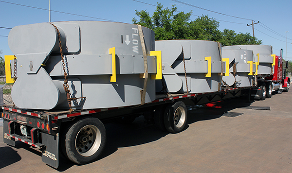
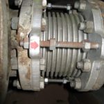
Single Expansion Joint Designed for a Refinery in Korea

Single Expansion Joint Designed for a Refinery in Korea

Type: Single Flanged Expansion Joint
Size: 18-1/2″ Long | 8″ Diameter
Material: 304 Stainless Steel | CS
Design 338°F @ 51 psig | 1-3/4″ Axial Movement | 225 lb. Spring Rate
Testing: 100% Dye Penetrant | Hydro-tested | X-Rayed

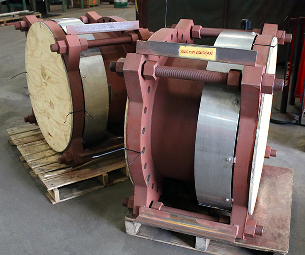
U.S. Bellows manufactured this single expansion joints for a refinery in Korea. The bellows were fabricated from 304 stainless steel and the frame from carbon steel. The expansion joint is 8″ diameter and 18-½” long. It is designed for an operating temperature of 338°F at 51 psig, with an axial movement of 1¾”, and a spring rate of 225 lb./in. The bellows were 100% X-rayed, dye-penetrant examined, and hydro-tested prior to shipment.

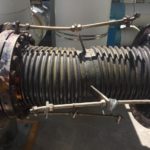
30″ Dia. Expansion Joints Designed for an Oil and Gas Facility

30" Dia. Expansion Joints Designed for an Oil and Gas Facility
Type: Single Expansion Joints
Size: 24″ F-F | 30″ Diameter
Design: 304 Stainless Steel | Carbon Steel
Material: 800°F @ 275 psig | 1″ Axial Compression
Testing: Hydro-tested

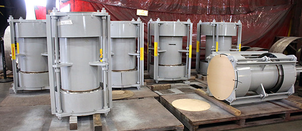
These single expansion joints were custom engineered for an oil and gas facility in Texas. The bellows, liner, and cover are fabricated from 304 stainless steel, while the flanges and tie rod assemblies from carbon steel. The units are 30″ in diameter, 24″ face-to-face and include control rods. They are designed for an operating temperature of 800°F at 275 psig and 1″ of axial compression. All expansion joints were hydro-tested prior to shipment.

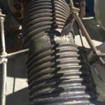
36″ Dia. Externally Pressurized Expansion Joints Designed for a Power Plant in Venezuela

36” Dia. Externally Pressurized Expansion Joints Designed for a Power Plant in Venezuela

Type: Externally Pressurized Expansion Joints
Size: 36″ I.D. | 56″ OAL | 10″ Face-to-Face
Design: Hastelloy C-276 Bellows | A36 CS Flanges & Spool
Material: 60 PSIG at 572°F | 9.75″ Axial Compression
Testing: 100% Dye-Penetrant | Hydro-Tested

U.S. Bellows custom designed externally pressurized expansion joints for a power plant in Venezuela. The units are 56″ in overall length and have a 36″ inside diameter. The bellows are fabricated from Hastelloy C-276 and the flanges and spool are A36 carbon steel. The units are designed for an operating pressure of 60 psig at 572°F and 9.75″ of axial compression. The expansion joints were 100% dye-penetrant tested and hydro-tested prior to shipment.

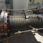
Thick-Wall Flanged and Flued Head Expansion Joints Designed for Boiler and Furnace Replacement

Thick-Wall Flanged and Flued Head Expansion Joints Designed for Boiler and Furnace Replacement

Type: Thick-Wall Flanged & Flued Head Expansion Joints
Size: 52-7/8″ I.D. | 83-5/8″ I.D. | 10″ Face-to-Face
Design: ASTM A 516-70 Carbon Steel
Material: 250″ Water Column
Testing: 100% Dye-Penetrant | Soap & Air Leak | Hydro-Tested

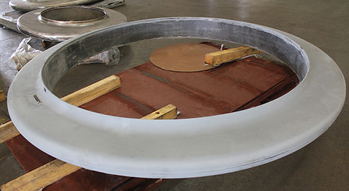
U.S. Bellows custom designed thick-wall flanged and flued head expansion joints for a boiler and furnace replacement at a chemical plant in Kentucky. The units were completely fabricated from ASTM A 516-70 carbon steel. The smaller unit’s inside diameter is 52-7/8″ and the larger unit is 83-5/8″. Both units are 10″ face-to-face. They are designed for an operating pressure of 250″ water column. The expansion joints were 100% dye-penetrant tested, soap & air leak tested, and hydro-tested prior shipment.

11 Foot Long Universal Gimbal Expansion Joints Designed for an Oil Refinery in Canada

11 Foot Long Universal Gimbal Expansion Joints Designed for an Oil Refinery in Canada

Type:  Universal Gimbal Expansion Joint
Size:  102″ – 133″ L | 41.5″ W | 41.75″ H | 32″ diameter
Material:  Carbon Steel | 304 Stainless Steel
Design:   100°F @ 285 psig | 102 lb/in/degree Rotational
Spring Rate | 15.4″ Lateral Deflection
Testing:   Hydrotested @ 428 PSIG

U.S. Bellows custom designed these universal gimbal expansion joints for an oil refinery in Canada. The bellows and liners are fabricated from 304 stainless steel, and the remainder of the components are fabricated from carbon steel. The units are 102″ and 133″ long respectively, and both are 41.5″ wide, 41.75″ tall, with 32″ OD. They are designed for an operating temperature of 100°F at 285 psig, with a 102 lb/in/degree rotational spring rate and 15.4″ of lateral deflection. The expansion joints were 100% dye-penetrant tested and hydro-tested at 428 psig prior to shipment.

Rectangular Metallic Expansion Joints Designed for an Exhaust Duct

Rectangular Metallic Expansion Joints Designed for an Exhaust Duct

Type: Rectangular Metallic Expansion Joint
Size: 16.5″ x 14.75″ x 12″ F-F
Design: 304 Stainless Steel
Material: Operating Temp: 800°F @ +/- 20″ WC
1″ Axial Compression | 0.25″ Angular Rotation
Testing: 100% Dye-penetrant tested | Soap & Air Tested

U.S. Bellows custom designed these rectangular metallic expansion joints for an exhaust duct application in Wisconsin. They are 16.5″ x 14.75″ and 12″ face-to-face. The units are completely fabricated from 304 stainless steel. They are designed for an operating temperature of 800°F at a +/- 20″ water column, with 1″ of axial compression and 0.25 degrees of angular rotation. The expansion joints were 100% dye-penetrant tested and soap & air tested prior to shipment.

Universal Expansion Joints Designed for a Tank Farm

Universal-Expansion-Joint-155090v2

Type: Universal Expansion Joint
Size: 24″ Dia. x 48″ F-F | 20″ Dai. x 50″ F-F
Material:  Carbon Steel | 316 Stainless Steel
Design: Operating Temperature: 180°F
Pressure: 264 PSIG
Movement: 2.75″ Lateral Deflection
Testing: 100% Dye-penetrant tested, X-rayed, Hydro-tested

These universal expansion joints were designed by U.S. Bellows for a tank farm application in Saudi Arabia. 16 of the units were 24″ dia. x 48″ face-to-face and 8 of the units were 20″ dia. x 50″ face-to-face. The bellows were fabricated from 316 stainless steel with the rest of the components from carbon steel. They are designed for an operating pressure of 264 psig at 180°F with 2.75″ of lateral deflection. The units were 100% dye-penetrant tested, x-rayed and hydro-tested prior to shipment.

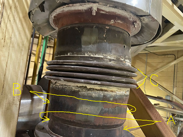
Refurbishment on a 72 Year Old Hinged Expansion Joint

Hinged expansion joint 166169

Type: Single Hinged Expansion Joint
Size: 26-3/4″ length x 42-1/2″ diameter
Material: CS | 304 SS | Inconel 625 LCF | Kaowool
Design Operating Temperature: 1,100°F
Pressure: 100 PSIG
Movement: 3° of Angular Rotation
Testing: Hydrotest at 100 PSIG

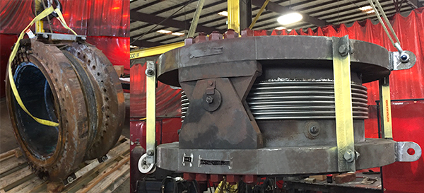
U.S. Bellows, Inc. refurbished a 72 year old single hinged expansion joint for a refinery in Louisiana. The expansion joint is 42-1/2″ in diameter and 25-3/4″ in length. The bellows are fabricated from Inconel 625 LCF, the liners are 304H stainless steel, the body is carbon steel and the insulation is Kaowool. The unit is designed for an operating pressure of 100 psig at 1,100°F and 3° angular rotation. A hydro test at 100 psig was conducted prior to shipping the unit after one week.

11 Foot Diameter Hinged Expansion Joints Designed for Vacuum Service in an Air-Cooled Condenser Unit in New York

Hinged expansion joint 152499

Type: Single Hinged Expansion Joints
Size: 64″ length x 127″ diameter
Material: Carbon Steel and 304 Stainless Steel
Design Operating Temperature Range: -10°F to 121°F
Pressure: 15 PSIG
Movement: 0.6° of Angular Rotation
Testing: 100% Dye Penetrant Test | Vaccum tested at 28.5″ of Mercury | 100% X-Rayed.

U.S. Bellows custom designed Single Hinged Expansion Joints for vacuum service in high-velocity steam and condensate duct for an air-cooled condenser unit in New York. The bellows are fabricated from a 304 stainless steel. The weld-ends and hardware are fabricated from carbon steel. The units are 127″ in diameter and 64″ overall length. They are designed for an operating pressure at full vacuum to 15 psi at -10 to 121°F and 0.6° of angular rotation. The units were vacuum tested at 28.5″ of mercury, 100% dye-penetrant examined, and the bellows longitudinal seams were 100% X-rayed.

24 Foot Long Universal Expansion Joint Custom Designed for a Steam Turbine

148702a1

Type: Rectangular metallic Universal Expansion Joint
Size: 291.75″ long x 62″ wide x 76″ high
Design:  Operating Temperature Range: 850°F
Pressure: 1.5 PSIG
Movement: 1.5″ Axial Compression
Material:  A36 Carbon Steel and 304 Stainless Steel
Testing: 100% Dye Penetrant Test and Pneumatic Test

U.S. Bellows custom designed this universal rectangular expansion joint for a steam turbine facility in Alaska. The bellows and liner were fabricated from 304 stainless steel and the weld ends from A36 carbon steel. The unit is 62″ wide, 291.75″ in length, and 76″ in height. It is designed for an operating temperature up to 850°F at 1.5 psig and 1.5″ of axial compression. The expansion joint was 100% dye-penetrant tested and pneumatic tested prior to shipment.

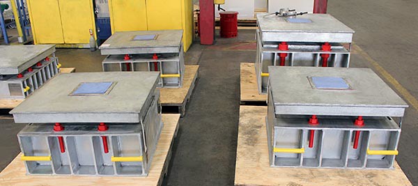
Big Ton Spring Supports for an Oil Refinery in Australia

PT&P Custom Designed Big Ton Spring Supports for an Oil Refinery in Australia


Type: Big Ton Spring Supports
Material: Carbon Steel w/ HDG Finish
Design: 13,457 lb. Load | 0.35″ Vertical
Testing: Load and Travel Tests

These big ton springs are used in supporting large heavy units such as compressors, vessels and pumps in power and petrochemical plants. The housing and frame are fabricated from carbon steel and hot-dipped galvanized, and the spring coils are dipped in a neoprene coating. The units are 48” x 40” x 20”. The big ton spring support is designed to allow limited movement of 0.35″ upwards and an operating load of 13,457 lb. This design saved the customer from having to entirely redesign the piping system, which saved them thousands of dollars. Load and travel tests were performed prior to shipping to an oil refinery in Australia.

Field Services – Expansion Joints

PPSM: Loading User Functions

HOW TO LOAD ALL PT&P SUPPORT SYMBOL PROCESSORS AND USER FUNCTIONS

*The following steps will navigate you through the corresponding bitmap forms.

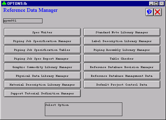
1) PDShell Form
* Select Reference Data Manager Option

Place support 1


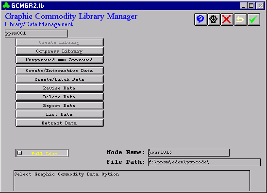
2) Reference Data Manager Form
* Select Graphic Commodity Library Manager Option

Load table 2


3) Graphic Commodity Library Manager Form
* Select Create/Interactive Data Option

Load table 4


4) Create Data
* Enter single file name or toggle between single file to a list of files; node name and file path must match the file’s directory.

Load table 4


5) Toggle From Single to List
* Enter ptpsupports.lis

* The file ptpsupports.lis is enclosed; make sure the node name and file path contain all the files in the list.

Load table 4

PPSM: Loading Tutorial Definition Forms

HOW TO LOAD TUTORIAL DEFINITION FORMS FOR ALL PT&P SUPPORTS

*The following steps will navigate you through the corresponding bitmap forms.

1) PDShell Form
* Select Reference Data Manager Option

Place support 1

2) Reference Data Manager Form
* Select Support Tutorial Definition Manager

Load table 2

3) Support Tutorial Definition Manager Form
* Select Create Data

Support Tutorial Definition Manager Form


4) Create Data
* Select List Data to toggle from Single to List

Load table 4


5) Support Tutorial Definition Manager Form
* Enter ptptdf.lis

Support Tutorial Definition Manager Form


6) Enter ptptdf.lis

* Enter single file name or toggle between single file to a list of files; node name and file path must match the file’s directory.

* Support Tutorial Definition Manager

* The file ptptdf.lis is enclosed; make sure the node name and file path contain all the files in the list.

Load table 4

Rectangular Rubber Expansion Joints for Centrifuge Suction and Discharge of Paraxylene Application at a Chemical Plant

Rectangular Rubber Expansion Joints for Centrifuge Suction and Discharge of Paraxylene Application at a Chemical Plant

Type: Rubber Expansion Joint
Size: 59.5″ x 20.25″ x 14″ FTF | 29.875″ x 22.75″ x 14″ FTF
Design: Viton Rubber | 304 Stainless Steel | Carbon Steel
Material: 250°F, 5 psig, & 0.25″ Axial & Lateral
Testing: Hydro-tested at 5 psig

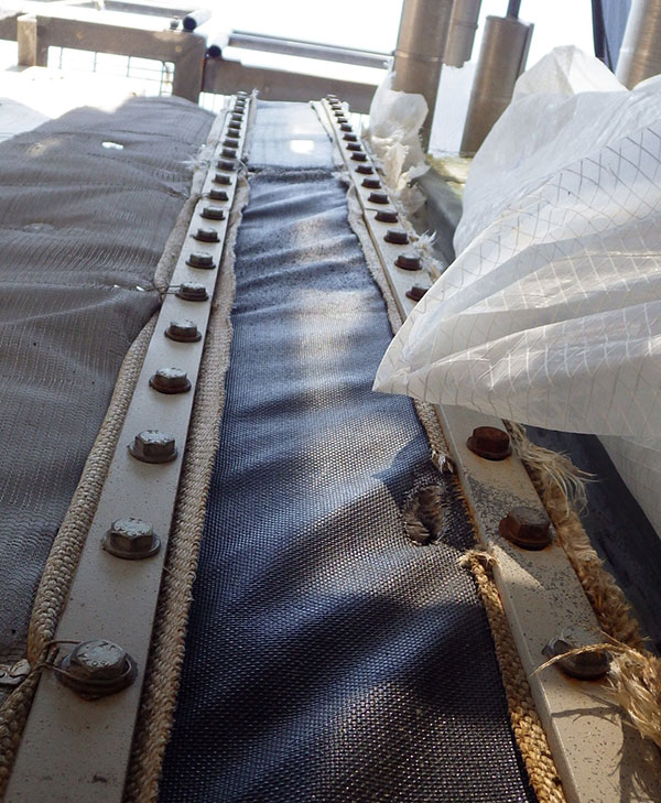
These rectangular Viton rubber expansion joints were custom designed for a suction and centrifuge discharge of paraxylene application at a chemical plant in India. The units are 59.5″ x 20.25″ x 14″ face-to-face and 29.875″ x 22.75″ x 14″ face-to-face. The belt material is made from Viton rubber with 304 stainless steel liner and carbon steel retaining bars. They are designed for an operating temperature up to 250°F at 5 psig, with 0.25″ of axial compression and lateral deflection. The units were hydro-tested to 5 psig prior to shipment.

PPSM: How to Load Reference Tables

HOW TO LOAD REFERENCE DATABASE TABLES 240-243 INTO PDS

*The following steps will navigate you through the corresponding bitmap forms.

1) PDShell Form
* Select Reference Data Manager Option

Place support 1


2) Reference Data Manager Form
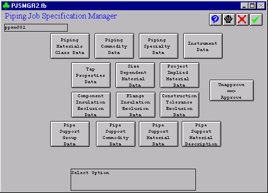
* Select Piping Job Specification Manager

Load table 2


3) Piping Job Specification Manager
* Select Piping Job Specification Manager

Load table 3


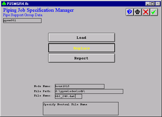
4) Pipe Support Group Data
* Select Pipe Support Group Data for Table 240

Load table 4


5) Pipe Support Group Data for Table 240
* Make sure to Report the existing table 240 first. Then copy and paste any additional items such as the PT&P supports into the file that was reported from the delivered table 240. Once the PT&P items have been added to the delivered Table 240, the new table can be loaded into PDS by choosing the Replace option above.

* Enter file name to replace the existing database Table; node name and file path must match the file’s directory.

Load table 5

PPSM: How to Load Forms

HOW TO LOAD ALL FORMS TO BE USED BY SUPPORT MODULE IN PDS

*The following steps will navigate you through the corresponding bitmap forms.

1) PDShell

Select all forms with the extension .fb and copy to delivered folder.

From Explorer, choose Tools => Find => Files or Folders => *.fb

Copy all the files to the directory where PDS forms are installed. Usually, C:\win32app\ingr\pdshell\forms

From File Manager, choose File => Search => *.fb

Copy all the files to the directory where PDS forms are installed. Usually, C:\win32app\ingr\pdshell\forms

2) Reference Data Manager

3) Support Tutorial Definition Manager

4) Create Data

5) Toggle from Single to List

6) *Enter ptptdf.lis

7) Accept by clicking the check mark


PPSM: How to Place Supports

PLACING PT&P VARIABLE SPRING HANGERS IN PDS (Plant Design System)

*The following steps will navigate you through the corresponding bitmap forms.

1) PDShell Form
* From the PDS main menu, choose Pipe Support Designer
* Alternate route: Choose Piping Designer >> File Options >> Switch to Pipe Supports
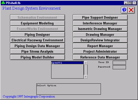
Place support 1


2) Pipe Support Modeling
* PT&P code can be downloaded from the below URL.
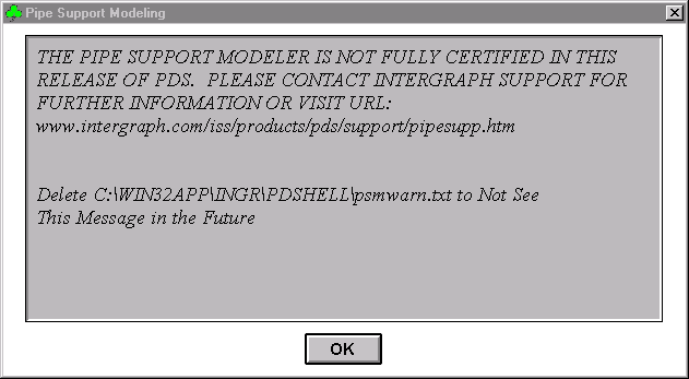
Place support 2


3) PPSM Place Support
* Choose the area in which to place pipe support.
* Choose the model in which to place pipe support.
* Choose Place Support from the Place menu.
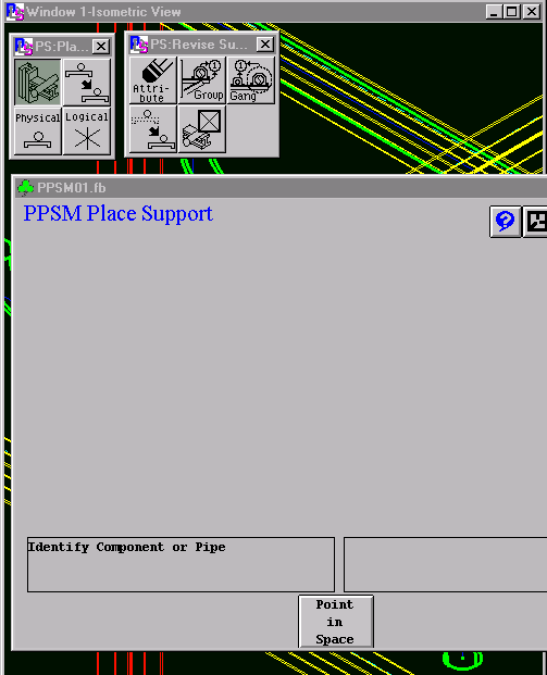
Place support 3


4) Identify Pipeline
* The form for placing asks for a pipeline to be identified. Choose a pipeline and confirm selection.
* Choose a support group. In this example, we will place a variable spring. Choose the Support Detail/Commodity box and enter a support number or tag.
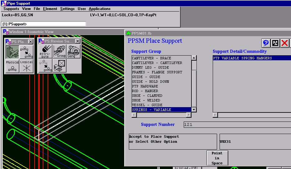
Place support 4


5) Choose Overhead Beam
* Choose an overhead beam to use as supporting steel. Tentative-click and then confirm the steel member.
* Fill the form parameters according to the below descriptions. These numbers are only used to demonstrate what inputs go into the form.
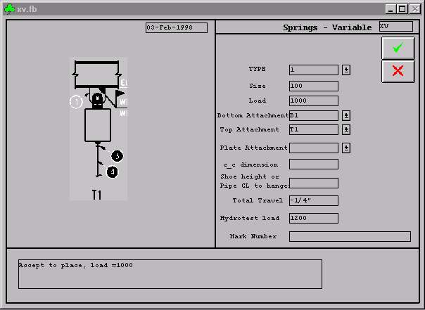
Place support 5


6) Using Forms & Their Options

HOW TO USE FORMS AND THEIR OPTIONS
XV FORM

TYPE —————————— Enter 1, 2, 4, 6, or 8 Depending on the PT&P type

SIZE —————————— Enter 0, 10, 20, …, 210, or 220 Depending on the PT&P size

LOAD —————————— Enter load in pounds as an integer ( 1000 ) without PT&P tare weight included

BOTTOM ATTACHMENT ——

B1 is a three bolt clamp

B2 is a lug for an elbow

B3 is a lug along the pipe

B4 is a trapeze assembly or PT&P type G

B5 is a base can supporting the pipe from below

TOP ATTACHMENT ————-

T1 is a PT&P type C hanger spring with a welded beam attachment, Fig. 20

T3 is a PT&P type A hanger spring with a welded lug attachment, Fig. 72

T4 is a PT&P type D that rests on top of a pair of channels with or without a support plate

TOP PLATE ATTACHMENT —

T5 is a 4X9 plate (for 3/8″ to ¾” rod sizes)

T6 is a 12×12 plate (for 7/8″ to 2-1/2″ rod sizes)

C-C DIMENSION —————— The centerline to centerline distance for a trapeze hanger

SHOE HEIGHT OR —————- Shoe height for B4 (trapeze type assembly) or

PIPE CL TO HANGER ———— Distance from pipe centerline to bottom of spring hanger for T3.

TOTAL TRAVEL —————— Total movement expected by the pipeline, upward is positive.


7) Accept The Form
* Accept the form by clicking the green check mark.
* The following graphics should appear in the model.
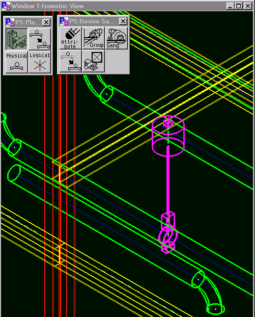
Place support 6

Custom Designed Single Expansion Joints for a Pipeline in China

Custom Designed Single Expansion Joints for a Pipeline in China

Type: Single Flanged Expansion Joint
Size: 41 3/8″ Length | 56.3″-76.75″ Diameter
Material: Incoloy 800 | 304H Stainless Steel
Design 1231°F | 15 psig | 2.624″ Axial & 0.25″ Lateral
Testing: Radiographic | Dye-penetrant | Hydro-tested at 23 psig

U.S. Bellows custom designed these single expansion joints for a pipeline in China. All units are 41 3/8″ length and vary in diameter from 56.3″-76.75″. The bellows were fabricated from Incoloy 800 and the weld ends from 304H stainless steel. They are designed for an operating pressure of 15 psig at 1231°F with 2.624″ axial compression and 0.25″ lateral deflection. The bellows and weld ends were 100% radiographic tested, 100% dye-penetrant tested, and hydro-tested at 23 psig prior to shipment

153″ Neoprene Expansion Joint for an Air Re-circulation/Ventilation Application at a Gas Turbine Facility in Hungary

153" Neoprene Expansion Joint for an Air Recirculation/Ventilation Application at a Gas Turbine Facility in Hungary

Type: Neoprene Expansion Joint
Size: 153″ x 55″ x 21″
Design: EPDM Reinforced Fabric Cloth | Carbon Steel
Material: 200°F, +/- 100″ WC, & 1″ Axial
Testing: Hydro-tested

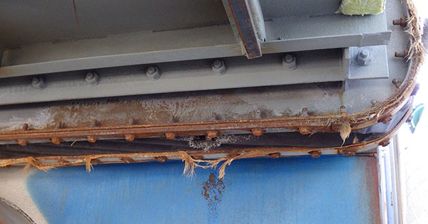
This EPDM neoprene expansion joint was designed for an air recirculation/ventilation application at a gas turbine facility in Hungary by U.S. Bellows. The unit is 153″ in length x 55″ width x 21″ face-to-face. The fabric belt is made from EPDM reinforced fabric cloth and the framework from A572 Gr. 50 carbon steel. It is designed for an operating temperature up to 200°F with a +/- 100″ water column and 1″ of axial compression and lateral deflection. The expansion joint was hydro-tested prior to shipment.
Top