Request A Quote

56 Externally Pressurized Expansion Joints for a Cooling System

56 Externally Pressurized Expansion Joints for a Cooling System

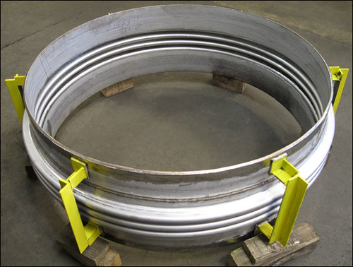
The externally pressurized expansion joints are 37.5″ in diameter and 36″ face-to-face. The bellows are 304 stainless steel, and the flange and ring are carbon steel. This expansion joint is rated for 232 psig with 5″ axial compression and temperatures up to 189°F. All bellows longitudinal welds were 100% x-rayed, all carbon steel welds were dye penetrant examined and each unit was hydro-tested to 348 psig. A total of 56 units were fabricated for a cooling system in a new university for women in the middle east

Single Expansion Joint For A Heat Exchanger

Single Expansion Joint For A Heat Exchanger

This 48-3/4″ diameter single metallic expansion joint will be used in a heat exchanger. The bellows are 321 stainless steel and the pipe is 304 L stainless steel. This expansion joint is rated for 145 psi with 1″ compression and temperatures up to 600°F. The unit was 100% x-ray tested, hydro-tested and 100% dye penetrant tested

How do you install an expansion joint?

The necessary steps for installing all expansion joints shall be pre-planned. The installers shall be made aware of these steps as well as the installation instructions furnished by the manufacturer. The most critical phases of the expansion joint installation are as follows.

  • Care shall be exercised to prevent any damage to the thin bellows section, such as dents, scores, arc strikes and weld spatter.

  • No movement of the expansion joint (compression, extension, offset, rotation and especially torsion) due to piping misalignment, for example, shall be imposed which has not been anticipated and designed into the movement capability of the expansion joint. If such movements are imposed, they can result in system malfunction, damage to the bellows or other components in the system. Specifically, cycle life can be substantially reduced, forces imposed on adjacent equipment may exceed their design limits, internal sleeve clearances may be adversely affected, and the pressure capacity and stability of the bellows may be reduced.

  • Any field pre-positioning shall be performed in accordance with specific instructions which include both the direction and magnitude of the movement.

  • Anchors, guides and pipe supports shall be installed in strict accordance with the piping system drawings. Any field variances from planned installation may affect proper functioning of the expansion joint and must be brought to the attention of a competent design authority for resolution.

  • The expansion joint, if provided with internal sleeves, shall be installed with the proper orientation with respect to flow direction.

  • After the anchors or other fixed points are in place and the piping is properly supported and guided, the expansion joint shipping devices should normally be removed in order to allow the expansion joint to compensate for changes in ambient temperature during the remainder of the construction phase.

High Temperature Fabric Expansion Joint Designed for an Exhaust Duct

113108v2a1
This rectangular fabric expansion joint will be used in an exhaust duct in a power plant. It measures 136″ L x 54″ W x 12″ face-to-face and is fabricated with stainless steel angle, frame ends, and internal liner. The fabric belt material is PTFE coated glass cloth, which is low friction and high in tear/crease resistance and tensile strength. This expansion joint is rated for an axial movement of 1-1/2″ with a lateral offset of 1/2″ and maximum temperatures up to 600°F. A quality inspection was administered, including a 100% dye-penetrant test prior to shipment.

Regarding various types of pipe clamp devices, are these devices also suitable for use with polymer material pipe?

Yes, pipe clamps are suitable for polymer material pipe, however the local stresses on the polymer material should first be evaluated by the client.

Two Bolt Pipe Clamps

How can I model your supports into CAESAR II?

Our spring hangers, constants, and variables are already in Caesar II – Rigid supports can be modeled as stops or restraints in the direction required.

How vital are pipe stess results to pipe support design?

This is a vital portion of the pipe support design. It provides us the loads that we need to design the pipe supports.

Stress Analysis of a Variable Spring Support

How much compressive strength does the marinite material permit?

4000 PSI is the recommended strength for marinite material.

Marinite Slide Plate

How do we inspect load cells and what is the criteria for their positioning?

A load cell is only the measuring device forcalibration and it is used to test all our spring cans and constants.

Where will the hold down supports be used?

A common application of hold down supports is on compressor applications or any where that vertical movement must be restricted but horizontal movement can be allowed.

42 Inch Hold Down with Wedge Support
42″ Hold Down with Wedge Support

What is the isolation pad material?

An isolation pad material isbelting material designed to absorb shock.

Isolation Pad on a Hold-Down Pipe Clamp

Does change in density imply change in thermal conductivity?

Yes, thehigher the density the higher the thermal conductivity.

We use a low pressure steam heater to heat rail cars at our asphalt terminal, will high temperature insulated pipe supports allow for proper expansion and contraction of the piping?

For this type of application, we recommend you use a high temperature support or hot shoes. Cold shoes are designed for up to about 200 degrees F. If you pick the correct design, it will allow for expansion and contraction of the pipe.

High Temperature
High Temperature Pipe Support

Is there a difference for drag force for hydraulic and mechanical snubber?

There is little difference in the initial drag force associated with mechanical and hydraulic snubbers. Basically, both styles are designed to impart a maximum of 2% of their design restraint load during normal pipe deflection.

Hydraulic Snubber
Hydraulic Snubber

Mechanical Snubber
Mechanical Snubber


Will the load of fluid flowing through the pipe be considered as a varying load? or is that included in the basic piping weight?

Yes the fluid will be considered as a varyingload. Additionally, when you design for the load, you include the weight of thepipe and the fluid flowing through it.

What is STAAD analysis?

STAAD analysis is a program we use for structural analysis, specifically to design auxiliary steel which is basically, the length between the structural steel designed by our engineering department and the extra supplementary steel required to support the additional supports which are beingutilized to support the piping system.

When you take a compression test to failure, what is the failure criteria?

The failure criteria is a permanentdeformation greater than 3% is considered a failure for that particular batch.

Is it practical to try to design a variable spring support or constant spring support for travel less than 0.1″?

It would not be recommended for a constant spring to be designed for less than 0.1″ for travel. Variable springs can accommodate that travel. The difference in load will be a function of thespring rate.

F-Type Variable Spring designed for 1/16 Inch Vertical Travel and 1/8 Inch Horizontal Travel
F-Type Variable Spring designed for 1/16″ Vertical Travel and 1/8″ Horizontal Travel

The dimensions of the support are checked as individual pieces or after it has been welded into a full assembly?

The answer to this is both. We check the individual pieces before we put the support together, then we check the final assembly before it ships.

Inspecting Permali Insulation Prior to Assembling Pipe Shoes

Will the load of fluid flowing through the pipe be considered as a varying load?

Yes the fluid will be considered as a varyingload. Additionally, when you design for the load, you include the weight of thepipe and the fluid flowing through it.

Top